
Structural Support of Rooftop Cooling Systems
A technical guide to the structural engineering of rooftop cooling systems. Learn about dunnage design, vibration isolation, wind/seismic anchorage, and waterproofing for mission-critical facilities.
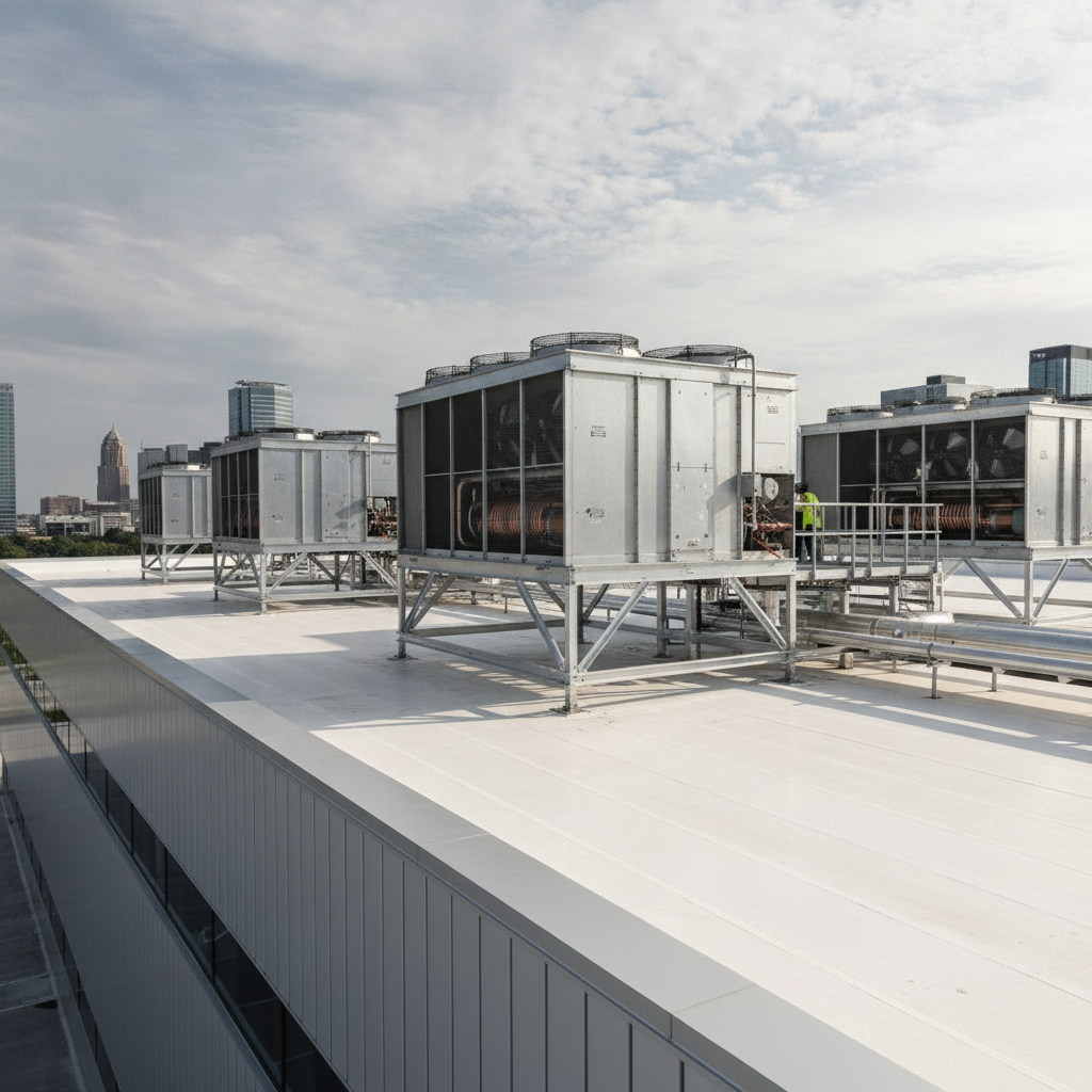
Aligning Equipment with Primary Structural Framing
The most fundamental principle of supporting heavy rooftop equipment is to transfer its load as directly as possible to the building’s primary vertical support elements. The ideal location for a heavy cooling tower or chiller is directly over a column line or a major girder. This strategy utilizes the strongest components of the primary structural framing to carry the load, minimizing stress on secondary members like joists and beams. Placing heavy equipment mid-span on roof joists or beams is highly inefficient and often infeasible. It can lead to excessive deflection, require significant reinforcement of the existing framing, and potentially compromise the performance of the roofing system. Early coordination between the mechanical and structural design teams is essential to align equipment layouts with the structural grid. This proactive approach avoids costly redesigns and ensures the load paths are clear, direct, and efficient, preventing over-stressing of lighter structural components and the roof deck itself.
Dunnage and Support Steel Design
Rooftop Equipment Support System Comparison
| Support Method | Key Design Considerations | Primary Application | Critical Coordination |
|---|---|---|---|
| Direct-to-Structure | Equipment must align perfectly with columns or main girders. Requires early layout commitment. | Single, very heavy units like large cooling towers or chillers. | Architectural, Mechanical, Structural |
| Dunnage Steel Frame | Distributes load to multiple points. Requires robust waterproofing at each support post. | Grouping multiple equipment units or supporting heavy equipment off-column lines. | Structural, Roofing, Mechanical |
| Equipment Rails | Typically proprietary, lighter-duty systems. Load capacity and distribution must be verified. | Lighter equipment like condenser units or exhaust fans that can span between joists. | Mechanical, Structural |
| Prefabricated Curbs | Integrates support and roof penetration. Must be sized for equipment weight and wind/seismic loads. | Packaged rooftop units (RTUs) with a defined footprint and down-flow duct connections. | Mechanical, Structural, Roofing |
| Vibration Isolation Curbs | Includes integrated spring or neoprene isolators within the curb assembly. Complex detailing. | RTUs or air handling units serving noise-sensitive spaces directly below. | Mechanical, Structural, Acoustical |
When direct alignment with primary framing isn’t possible or when multiple pieces of equipment need to be grouped together, a dunnage steel frame is the standard solution. Dunnage is a structural framework, typically made of hot-dip galvanized or painted structural steel, that sits on the roof. Its purpose is to collect the loads from the equipment and distribute them to specific, pre-determined strong points in the roof structure below. The design of dunnage must account for the equipment’s static weight, operating weight (including water), and loads from wind and seismic events. The frame must also be designed to provide adequate clearance for roofing and maintenance, and its height is often dictated by snow drift or wind-driven rain considerations. The structural engineer of record designs the dunnage frame, its connections, and its anchorage to the building structure, ensuring all components comply with relevant standards like the AISC 360 Specification for Structural Steel Buildings.
Vibration Isolation and Dynamic Loads
Rooftop cooling systems contain rotating components like fans and compressors that generate significant vibration. If not properly managed, this vibration can transmit through the building structure, causing audible noise, occupant discomfort, and even fatigue damage to structural and non-structural components. A critical aspect of the support design is therefore vibration isolation. This is achieved by installing isolators—such as calibrated springs, neoprene pads, or more complex assemblies—between the equipment and its support structure. The selection of the isolator depends on the equipment’s operating frequency, weight, and the sensitivity of the space below. The structural design must account for these dynamic loads and ensure that the support framing is stiff enough to prevent structural resonance, a condition where the framing’s natural frequency matches the equipment’s operating frequency, leading to amplified vibrations.
Wind and Seismic Anchorage Requirements
In addition to vertical gravity loads, rooftop equipment must be securely anchored to resist lateral loads from wind and seismic events. These forces can be substantial, particularly for tall equipment with a large surface area. The structural engineer calculates these loads based on model building codes and standards like ASCE 7, considering factors such as the building’s geographic location, height, and the equipment’s size, shape, and weight. Design parameters for these lateral forces, including wind speeds and seismic ground motion values, are site-specific and vary by jurisdiction. Every project team must confirm the applicable standards with the local, state, regional, and federal authorities that hold review authority over the site and reference the project’s adopted building codes. The anchorage design involves specifying the size, type, and embedment of bolts or the details of welded connections required to transfer these forces from the equipment frame into the dunnage or building structure, ensuring the unit remains in place during a design-level event.
Roof Penetrations and Structural Framing
Supporting the equipment is only part of the challenge; providing a path for pipes, conduits, and ducts creates another set of structural issues. Every opening cut into the roof deck for these services is a roof penetration that can compromise structural integrity and create a potential leak path. The structural design must include details for reinforcing the framing around these openings. For larger openings, this may involve adding new steel beams and headers to frame the opening, ensuring that loads are properly transferred around the void. For smaller penetrations through a metal deck, specific reinforcement may be required to maintain the diaphragm capacity of the roof deck. This work requires careful MEP coordination to consolidate penetrations where possible and ensure that the structural reinforcement is designed and installed correctly before roofing work begins.
Curb Detailing and Integrated Waterproofing
The interface between the equipment support and the roofing membrane is one of the most common sources of roof leaks. To prevent water intrusion, supports typically penetrate the roof via equipment curbs. A curb is a raised frame, typically made of wood or metal, that is anchored to the roof structure. The roofing membrane is then run up the sides of the curb and counter-flashed to create a watertight seal. Meticulous detailing of these connections is paramount. The design documents must clearly specify the curb construction, height, flashing requirements, and integration with the roof membrane. The structural engineer, architect, and roofing consultant must collaborate to ensure the curb is structurally sound, properly located, and detailed in a way that is compatible with the specified roofing system. This coordination ensures a durable, watertight seal that protects the facility for its entire service life.
The RSP Engineers Integrated Design Process
At RSP Engineers, we approach the design of rooftop equipment supports through a lens of integrated design. Our process begins with early and frequent collaboration between our structural engineers and the project’s mechanical, architectural, and roofing design teams. We leverage Building Information Modeling (BIM coordination) to create a unified digital model of the building, allowing us to detect and resolve clashes between equipment, support steel, and primary framing long before construction begins. This proactive approach facilitates optimal equipment placement, efficient load path design, and fully coordinated penetration details. Our constructability reviews ensure that the proposed support system is not only structurally sound but also practical to build and easy to waterproof. By integrating these disciplines, we mitigate risks, prevent costly change orders, and deliver a robust, reliable, and watertight solution for mission-critical facilities.
Common Issues and Mitigation Strategies
Even with a solid design, several common issues can arise during construction and operation. Proactive planning and quality control are key to avoiding them. Roof Leaks: The most frequent problem, typically occurring at support penetrations or improperly detailed curbs. Mitigation involves rigorous design review of flashing details, pre-installation meetings with the roofing contractor, and stringent field quality control. Vibration Transmission: Occurs when isolators are incorrectly selected, installed, or short-circuited (e.g., by a rigid conduit connection). Mitigation requires proper engineering selection of isolators and inspection to ensure they are installed per manufacturer instructions and free of bridging. Anchorage Failure: During a high-wind or seismic event, improperly installed anchors can fail. Mitigation includes clear specifications for anchor types, installation procedures, and special inspections by a qualified third party to verify compliance. Corrosion: Support steel exposed to the elements can corrode, compromising its strength. Mitigation involves specifying appropriate protective coatings, such as hot-dip galvanizing, and designing details that prevent water from pooling on steel surfaces. Frequently Asked Questions How early should structural design for rooftop equipment begin? Structural coordination should begin as soon as the preliminary mechanical equipment layout and specifications are available, typically during the schematic design phase. Early involvement allows the structural grid to be optimized for equipment loads, minimizing costly reinforcement later in the project. What is the difference between dunnage and a simple equipment curb? A curb is typically a perimeter frame used to mount a single piece of equipment and provide a raised, waterproofed opening for ductwork or piping. Dunnage is a more extensive structural steel frame designed to support one or more pieces of equipment and distribute their weight over a wider area to specific structural members. Who is responsible for waterproofing the equipment supports? This is a shared responsibility. The architect and roofing consultant design the waterproofing details. The structural engineer designs the supports to be compatible with those details. The roofing contractor is responsible for the correct installation, and this work should be reviewed by the design team and a third-party inspector. Can we add more cooling units to an existing roof? Possibly, but it requires a thorough structural analysis of the existing roof framing to determine if it has sufficient reserve capacity. A Professional Engineer must evaluate the structure and design any necessary reinforcements. Simply placing new equipment without analysis can lead to overstress and potential failure. What information does the structural engineer need from the mechanical equipment supplier? The structural engineer needs a technical submittal or ‘cut sheet’ that provides the equipment’s precise dimensions, footprint, weight (both shipping and operating), center of gravity, and the location and size of all support points. For seismic design, information on lateral force resistance may also be required. Partner with RSP Engineers for Your Mission-Critical Facility Design Successfully integrating large-scale cooling systems requires a deep understanding of structural behavior, building envelope science, and interdisciplinary collaboration. The RSP Engineers team has the expertise to navigate these complexities. We provide comprehensive structural engineering, MEP coordination, and site development services for the most demanding projects. Our integrated approach ensures that your facility’s critical infrastructure is supported by a robust, reliable, and resilient design. Contact us to discuss how we can support your next mission-critical facility. Conclusion The structural support of rooftop cooling systems is a complex engineering challenge that is critical to the long-term performance and reliability of a facility. Success hinges on a holistic approach that goes beyond simple gravity load calculations. By focusing on integrated design from the project’s inception, carefully considering dynamic and environmental loads, and meticulously detailing the waterproofing interface, project teams can deliver a solution that ensures structural integrity and protects the valuable assets within the building. This attention to detail is the hallmark of quality engineering and is essential for achieving the long-term performance required by today’s advanced facilities. Related Articles Structural Framing Considerations for Data Center Mechanical Equipment Minimizing Differential Settlement Risks on Data Center Campuses A Guide to Geotechnical Settlement Analysis for Data Center Buildings
FAQs
-
Structural Support of Rooftop Cooling Systems requires careful planning, qualified engineering, and compliance with the applicable codes and permits.
-
Getting Structural Support of Rooftop Cooling Systems right protects safety, supports regulatory compliance, and avoids costly redesigns or delays.
-
RSP Engineers provides licensed expertise and end-to-end support for Structural Support of Rooftop Cooling Systems, from early planning through permitting.