
Rigging Routes for Data Center Generators and Transformers
Expert civil engineering insights on planning rigging routes for heavy data center equipment like generators and transformers. Learn about ground bearing, utility protection, and sequencing.
The Civil Engineer’s Role in Rigging Route Design
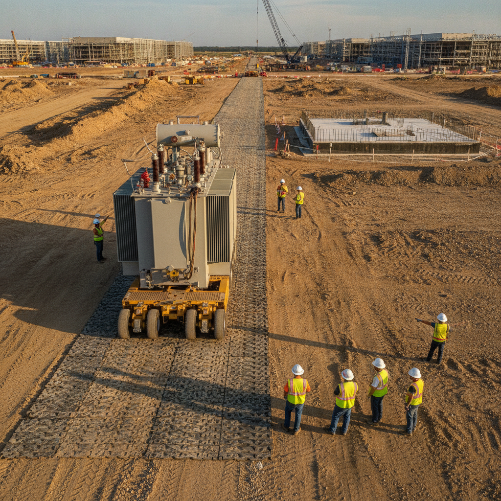
The path of least resistance is rarely a straight line on a complex construction site. The civil engineering team’s role is to define a viable, engineered path that accounts for the immense loads involved. This process begins during the initial site plan design, long before any equipment is ordered. The site layout must anticipate these delivery paths, ensuring that roadways, laydown areas, and the final routes to equipment pads are designed with sufficient width, turning radii, and structural capacity. Key responsibilities include integrating the rigging route into the overall site grading and drainage design. The route must be relatively flat and stable, avoiding steep slopes or areas with poor drainage that could compromise subgrade integrity. Furthermore, the placement of permanent site features like light poles, fire hydrants, security bollards, and landscaping must be carefully considered to avoid creating permanent obstacles. Proactive planning by a Professional Engineer ensures the rigging operation is a predictable, engineered event rather than a high-risk improvisation.
Ground Bearing Pressure and Subgrade Preparation
Key Considerations for Rigging Route Analysis
| Component | Civil Engineering Challenge | Mitigation Strategy |
|---|---|---|
| Equipment Load & Transport | Extreme point loads exceeding standard pavement or subgrade capacity. Large turning radii. | Detailed geotechnical analysis, use of load-spreading mats, subgrade improvement, and vehicle path modeling. |
| Subgrade & Soil Conditions | Low bearing capacity, potential for settlement, or shear failure under load. | Conducting a soil boring test, specifying engineered fill, and designing a temporary matting system. |
| Underground Utilities | Risk of crushing critical electrical duct banks, stormwater pipes, and pressurized lines. | Comprehensive utility mapping (SUE), structural analysis of crossings, and designing protective bridging or reinforcement. |
| Surface Structures & Clearances | Conflicts with buildings, light poles, overhead lines, and temporary construction elements. | 3D clash detection analysis, establishing exclusion zones, and integrating the route into the master site plan design. |
| Construction Phasing | The planned route becomes blocked by other construction activities before the move. | Integrating the rigging schedule into the master project schedule and protecting the route as a dedicated logistics corridor. |
| Transfer & Offload Points | Insufficient space or unstable ground at the point of transfer from truck to transporter or for the final crane lift. | Designing dedicated, reinforced laydown and crane pads as part of the initial civil engineering scope. |
Generators and transformers can weigh hundreds of tons, exerting immense pressure on the ground. The primary technical challenge is ensuring the subgrade along the rigging route can support these concentrated loads without failure. This requires a thorough Geotechnical Engineering investigation to understand soil types, compaction levels, and load-bearing capacity. The geotechnical soil report is a foundational document for this analysis, providing critical data for the civil engineering design. Based on the geotechnical analysis, the route may require significant preparation. This can include over-excavation and replacement with engineered fill, chemical stabilization, or the use of geogrid reinforcement. In nearly all cases, temporary load-spreading systems are necessary. These often consist of heavy-duty timber or composite crane mats that distribute the load over a wider area, reducing the ground bearing pressure to acceptable levels. It is critical to note that soil conditions and preparation requirements vary by jurisdiction, and every project team should confirm the applicable standards with the local, state, regional, and federal authorities that hold review authority over the site. A detailed analysis prevents costly equipment rollovers and subgrade failures.
Protecting Subsurface Infrastructure
One of the greatest risks during a heavy lift operation is damage to buried utilities. A typical data center site has a dense network of underground infrastructure, including electrical duct banks, communication conduits, stormwater management systems, and pressurized water and sewer lines. The rigging route will inevitably cross some of these critical systems. A direct load from a transporter can easily crush pipes and conduits, leading to expensive repairs and severe project delays. The first step is a comprehensive utility survey to accurately map all subsurface infrastructure. The civil engineering plans must clearly identify these crossings. For each crossing, an engineering analysis is performed to determine if the utility can withstand the anticipated load. If not, mitigation measures are required. These can include using thick steel plates to bridge the utility trench, installing temporary culverts, or designing custom concrete caps to protect critical duct banks. Protecting this infrastructure is a non-negotiable part of utility coordination and risk management.
Navigating Vertical and Horizontal Clearances
A successful rigging route must account for three-dimensional space. The analysis cannot be limited to the ground plane. The project team must verify adequate horizontal and vertical clearances along the entire path. Horizontal constraints include permanent buildings, temporary construction trailers, material laydown areas, and site fencing. The turning radii of the transport vehicle, often a self-propelled modular transporter (SPMT), must be carefully modeled to ensure it can navigate corners without encroaching on restricted areas. Vertical clearance is equally important. The route must be free of overhead power lines, communication cables, pipe racks, and other aerial obstructions. The combined height of the transporter and the equipment must be calculated and checked against all potential overhead conflicts. This analysis should be part of the initial site development plan and continuously updated as construction progresses. Using 3D modeling and clash detection software is an effective way to visualize the entire move and identify potential conflicts before the equipment arrives on site.
Sequencing and Phasing: Keeping the Path Clear
A perfectly designed rigging route is useless if it is blocked when the equipment arrives. The timing of the equipment delivery must be tightly integrated with the overall construction schedule. This is a critical aspect of construction administration and requires constant communication between the general contractor, subcontractors, and the design team. The rigging route must be treated as a protected corridor, with clear rules about when other trades can access or cross it. For example, the installation of underground utilities must be completed and backfilled properly before the route is prepared. The erection of steel or placement of permanent site furnishings along the path must be delayed until after the move is complete. The civil engineering team often helps develop a detailed phasing plan that explicitly shows the state of the site at the time of the rigging operation, ensuring the path remains clear and unobstructed. This proactive scheduling prevents last-minute conflicts and costly stand-by time for specialized transport crews.
How RSP Engineers Approaches Rigging Route Planning
At RSP Engineers, we view rigging route planning as an integral part of our comprehensive site engineering services. Our process is built on proactive collaboration and detailed technical analysis to de-risk this critical project phase. We begin by engaging with the client, equipment vendors, and rigging contractor during the earliest design stages to understand the specific equipment dimensions, weights, and transport methods. This allows us to incorporate the necessary geometric and structural requirements directly into the site design. Our approach involves a detailed review of the Geotechnical soil report, comprehensive mapping of all existing and proposed utilities, and the development of a detailed rigging route plan and profile. We model the path to verify clearances and turning movements, and we design specific engineering solutions for any utility crossings or areas of weak subgrade. By integrating this critical logistics plan into the core civil engineering documents, we provide our clients with a clear, executable strategy that protects their investment and keeps the project on schedule.
Common Issues in Rigging Route Execution
Despite careful planning, several common issues can arise during the execution of a heavy equipment move. One of the most frequent is the discovery of undocumented or incorrectly located underground utilities, which can halt the operation immediately. Another common problem is inadequate subgrade preparation, where assumptions about soil strength prove incorrect, leading to matting failure or transporter instability. This highlights the importance of a thorough Geotechnical Engineering study and proper quality control during site work. Construction sequencing conflicts are also a major source of problems. A subcontractor may inadvertently place a material stockpile or dig a trench across the designated route, requiring emergency remediation. Finally, a failure to account for the dynamic loads and turning forces of the transport equipment can lead to damage to adjacent curbs, pavement, or structures. These issues underscore the need for a dedicated plan and continuous oversight from an experienced Professional Engineer during the operation.
Partner with RSP Engineers for Your Mission-Critical Project
Ensuring the safe and timely delivery of critical equipment is fundamental to the success of your data center project. Don’t leave this complex operation to chance. The team at RSP Engineers provides the expert civil engineering, site development planning, and detailed utility coordination required to design and implement robust rigging routes. We collaborate with your team to mitigate risks, protect site infrastructure, and facilitate a smooth installation process. Contact us today to discuss how our site engineering services can support your next mission-critical facility.
Conclusion
Rigging route planning for data center generators and transformers is a specialized discipline that blends civil engineering, geotechnical analysis, and construction logistics. A successful move is the result of proactive design, detailed technical assessment, and seamless coordination among all project stakeholders. By addressing ground bearing pressures, protecting subsurface utilities, and integrating the move into the construction sequence, project teams can avoid costly damage and delays. Ultimately, a well-engineered rigging route is a critical investment in project certainty and asset protection, ensuring your facility’s core equipment arrives safely at its foundation.
FAQs
-
A rigging route study is a comprehensive engineering analysis that defines and validates a safe path for moving heavy equipment from a delivery point to its final installation location. It includes a geotechnical analysis of soil conditions, a structural assessment of any surfaces or utilities being crossed, a clearance check, and a detailed logistics plan.
-
The design is a collaborative effort, but the civil engineering firm typically leads the on-site portion. They work closely with the project’s structural engineer, the rigging contractor who understands the transport equipment, and the Geotechnical engineer who provides data on soil capacity. The general contractor is responsible for executing the plan.
-
As early as possible. Ideally, rigging routes should be considered during the conceptual site plan design phase. This allows the site layout, grading, and utility placement to be optimized to accommodate the move, which is far more cost-effective than trying to retrofit a solution onto a nearly complete site.