
Data Center Slab-on-Grade Design Considerations
A technical guide for data center developers on slab-on-grade design, covering subgrade prep, heavy load reinforcement, joint layout, flatness criteria, and utility integration.
The Foundation of Performance: Subgrade Preparation and Modulus
The long-term performance of any slab-on-grade begins with the soil beneath it. Proper subgrade preparation is non-negotiable for data centers, where even minor differential settlement can compromise equipment and structural integrity. The process starts with a comprehensive geotechnical investigation, which provides critical data on soil types, bearing capacity, and potential settlement issues. The resulting geotechnical soil report is the foundational document for both the civil engineering site work and the structural slab design. A key parameter derived from this investigation is the Modulus of Subgrade Reaction (k-value), which measures the stiffness of the soil foundation. A uniform and high k-value is essential for minimizing slab deflection under heavy loads. Achieving this requires meticulous earthwork, including the removal of unsuitable materials, moisture conditioning of soils, and placement of engineered fill in controlled lifts. Each lift must be compacted to a specified density, verified through field testing, to ensure the subgrade provides consistent support across the entire building footprint. Proof-rolling with heavy equipment is often used as a final validation step to identify any remaining soft or unstable areas before the slab is placed.
Controlling Moisture Intrusion with High-Performance Vapor Retarders
Comparison of Slab Reinforcement Options
| Reinforcement Type | Primary Function | Key Advantages | Design Considerations |
|---|---|---|---|
| Welded Wire Reinforcement (WWR) | Shrinkage and temperature crack control | Cost-effective for light-duty slabs; quick to place. | Must be properly supported to ensure correct placement within the slab; offers minimal structural capacity. |
| Rebar (Reinforcing Steel) | Structural capacity and crack width control | Provides significant flexural strength to handle heavy point and uniform loads; well-understood design process. | More labor-intensive to install than WWR; placement and spacing are critical for performance. |
| Steel or Synthetic Fibers | Multi-directional crack control; impact resistance | Distributes reinforcement throughout the entire concrete matrix; can reduce shrinkage cracking and improve durability. | Can affect concrete finishability; engineering design required to replace conventional reinforcement. |
| Post-Tensioning (PT) | Actively compresses the slab to eliminate cracks | Allows for thinner slabs and significantly longer joint spacing (or joint-free slabs); excellent for controlling cracks under heavy loads. | Requires specialized designers and contractors; more complex installation and stressing process. |
Moisture is the enemy of sensitive electronic equipment. Uncontrolled moisture vapor transmission through a concrete slab can lead to corrosion, electrical shorts, and an environment conducive to microbial growth. To prevent this, data center slabs require a high-performance vapor retarder installed directly beneath the concrete. This is distinct from simple polyethylene sheeting used for dampproofing; a true vapor retarder is an engineered material manufactured to meet stringent industry standards like ASTM E1745 for permeance, puncture resistance, and tensile strength. Proper installation is as critical as material selection. All seams must be overlapped and sealed according to the manufacturer’s specifications, and any penetrations for conduits or pipes must be meticulously detailed and sealed to create a monolithic barrier. The decision to place the concrete directly on the vapor retarder versus placing a sand blotter layer between them is a key design choice. While a blotter layer can aid in concrete curing, it can also become a moisture reservoir, negating the retarder’s benefit. For most data center applications, a direct-contact placement is preferred to maximize moisture protection for the operational facility.
Designing for Heavy and Concentrated Equipment Loads
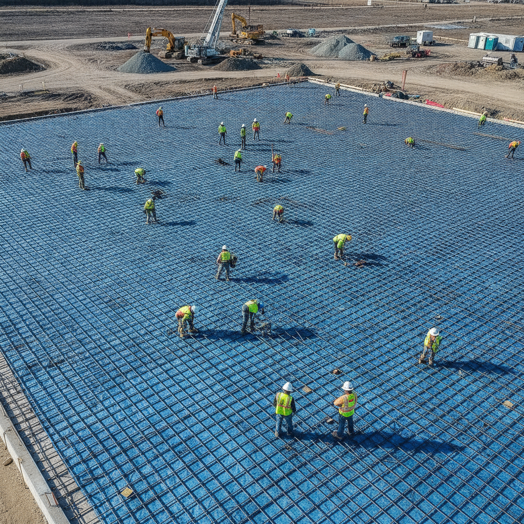
Data centers are characterized by immense and highly concentrated loads from server racks, power distribution units (PDUs), uninterruptible power supply (UPS) systems, and cooling equipment. The slab thickness design and reinforcement strategy must account for these specific loads, not just a generic uniform load. The structural engineer of record will analyze the equipment layout to determine the worst-case loading scenarios, including point loads from equipment feet and wheel loads from pallet jacks used during installation and maintenance. This analysis dictates the required concrete compressive strength, slab thickness, and the type and amount of reinforcement. Common reinforcement strategies include conventional reinforcing steel (rebar), welded wire reinforcement (WWR), steel fibers mixed into the concrete, or post-tensioning. Each approach has distinct advantages for controlling cracking, enhancing load-carrying capacity, and managing construction costs. The final reinforcement design is a critical component of the overall structural engineering package, ensuring the slab can support the facility’s full operational weight without excessive cracking or deflection.
Joint Layout, Load Transfer, and Crack Control
Concrete naturally shrinks as it cures, creating internal stresses that can lead to random cracking. A well-designed joint layout is essential to control where these cracks occur. The slab is divided into panels with control joints (saw-cut or formed) that create weakened planes for cracks to form in straight, manageable lines. The spacing and depth of these joints are carefully calculated based on the slab thickness and concrete properties. Slab design and jointing practices are governed by a combination of model building codes and industry standards, but specific requirements can vary by jurisdiction. Project teams must confirm all applicable standards with the authority having jurisdiction and the project’s structural engineer of record. In areas with heavy forklift or equipment traffic, preventing the vertical movement of slab panels at the joints is crucial. This is achieved through load transfer mechanisms. Traditional round dowel bars are effective, but plate dowels or diamond-shaped dowels are often preferred in data centers as they allow for lateral slab movement from shrinkage while still providing vertical support. Proper load transfer prevents joint spalling (chipping) and eliminates tripping hazards, maintaining a safe and functional surface for the life of the facility and preventing differential settlement between slab panels.
Achieving Strict Flatness and Levelness Tolerances
The proper installation and operation of server racks and other sensitive equipment depend on an extremely flat and level floor. The industry measures these characteristics using floor flatness (FF) and floor levelness (FL) numbers, as defined by standards like ACI 117. While a typical warehouse might specify FF 35 / FL 25, a data center often requires ‘superflat’ or ‘very flat’ floors, with specifications of FF 50 / FL 35 or even higher, particularly in equipment corridors and data halls. Achieving these tight construction tolerances requires specialized construction techniques. This includes the use of laser-guided screeds to place the concrete, highly skilled finishing crews, and a meticulous quality control process. The concrete mix design itself is also a factor, as mixes prone to high shrinkage can lead to curling at the slab edges, compromising the specified flatness. Meeting these stringent requirements is critical for ensuring that server racks align perfectly and that heavy rolling equipment can move safely and efficiently without jarring sensitive components.
Integrating Underslab Utilities and Penetrations
Beneath the seemingly simple surface of a data center slab lies a complex network of underslab utilities. This includes electrical conduits for power and data, piping for chilled water or other liquid cooling systems, and an extensive grounding grid. The layout of these utilities must be precisely coordinated early in the design phase to avoid conflicts and ensure proper placement before the slab is poured. This requires intensive MEP coordination between the civil, structural, mechanical, and electrical engineering teams. Every pipe, conduit, or grounding wire that passes through the slab creates a penetration that must be carefully detailed. These slab penetrations can weaken the slab and create pathways for moisture intrusion if not handled correctly. The design must specify proper block-outs, reinforcement around openings, and methods for sealing the penetration to maintain the integrity of both the concrete slab and the underlying vapor retarder. Failure to plan for this integration can lead to costly and time-consuming rework on site.
The RSP Engineers Approach to Slab-on-Grade Design
At RSP Engineers, we recognize that a data center slab is a critical asset, not a commodity. Our process begins with a deep dive into the project’s specific requirements, including a thorough review of the geotechnical soil report and the planned equipment loading. We facilitate close collaboration between the Geotechnical engineer, structural engineer, architect, and MEP designers to ensure a fully integrated design. Our team focuses on developing a robust and constructible slab system that balances performance with project economics. We provide detailed specifications for subgrade preparation, vapor retarder installation, concrete mix design, reinforcement, and jointing. During construction, we offer construction administration services to verify that the work is executed according to the design intent, helping to ensure the final product meets the stringent demands of a mission-critical facility.
Common Issues and Mitigation Strategies
Even with a solid design, several issues can arise during and after construction. Uncontrolled random cracking is often caused by improper joint spacing or timing of saw cuts. Slab curling, where the edges of a slab panel lift off the subgrade, results from differential drying and can be mitigated with proper curing techniques and a low-shrinkage concrete mix. Moisture-related problems are almost always traced back to a compromised or improperly specified vapor retarder. Finally, joint spalling and deterioration are typically due to inadequate load transfer mechanisms or heavy, hard-wheeled traffic on joints that have not been properly filled.
Partner with RSP for Your Mission-Critical Facility
Designing and engineering the foundation for a mission-critical facility demands precision, experience, and a deep understanding of the unique challenges involved. The RSP Engineers team provides the expert civil engineering and site development services needed to support complex projects. We excel at structural coordination, utility integration, and delivering designs that ensure long-term performance and reliability. Contact us to discuss how we can support your next data center project from the ground up.
Conclusion: A Foundation for Digital Infrastructure
The slab-on-grade is the unsung hero of the data center, providing the stable, reliable platform upon which the digital world is built. Its design involves a complex interplay of geotechnical conditions, structural loads, moisture control, and exacting construction tolerances. A successful outcome depends on a holistic approach that integrates a thorough geotechnical investigation, robust structural engineering, and diligent construction administration. By prioritizing these critical design considerations, developers and operators can ensure their facility is built on a foundation engineered for resilience and uptime.
FAQs
-
The three most critical factors are a uniformly prepared subgrade with a known stiffness (k-value), a design that accounts for the specific heavy and concentrated loads of the data center equipment, and a properly installed high-performance vapor retarder to protect sensitive electronics from moisture.
-
There is no single answer, as the thickness is a result of a detailed structural analysis. It depends on the soil support conditions (subgrade modulus), the magnitude and type of equipment loads, the concrete strength, and the reinforcement strategy. Slabs can range from 6 inches for lighter-duty areas to 10 inches or more in zones with heavy UPS or cooling equipment.
-
A data center’s controlled environment is critical for equipment reliability. Moisture vapor migrating through the concrete slab can increase humidity, cause condensation, and lead to corrosion of electronic components. A properly specified and installed vapor retarder is the primary defense against this damaging moisture intrusion.