
Wind Design for Data Center Facilities
A technical guide to wind design for data center facilities. Learn about Risk Category, MWFRS vs. C&C, roof uplift, and designing beyond code for mission-critical resilience.
Establishing the Design Wind Speed and Risk Category
The foundation of any wind-resistant design is determining the appropriate loads the structure must withstand. This process begins with establishing the design wind speed, which is derived from wind speed maps provided in consensus-based standards like ASCE 7, “Minimum Design Loads and Associated Criteria for Buildings and Other Structures.” These maps are based on historical meteorological data and provide basic wind speeds for different geographic locations across the United States. However, the basic wind speed is only one part of the equation. The building’s intended use and the consequences of its failure are quantified by its Risk Category. While a standard office building might be a Risk Category II, a data center—due to its critical role in business and communication infrastructure—is typically classified as Risk Category III or IV. This higher classification mandates the use of a greater importance factor, which effectively increases the design wind pressures, ensuring a more robust structure. The selection of the correct Risk Category is a crucial first step that influences every subsequent aspect of the structural and envelope design. Permitting requirements and code interpretations for these classifications vary by jurisdiction, and every project team should confirm the applicable standards with the local, state, regional, and federal authorities that hold review authority over the site.
Differentiating MWFRS and Components & Cladding (C&C)
Key Wind Design Parameters: Code Minimum vs. Enhanced Resilience
| Parameter | Standard Approach (Code Minimum) | Enhanced Resilience Approach |
|---|---|---|
| Risk Category | Category III, based on the critical nature of operations as defined by the building code. | Category IV, treating the facility as essential for community safety and recovery, resulting in higher load factors. |
| Design Wind Speed | Based on the code-mandated return period (e.g., 700-year MRI for RC III). | Designed for a longer return period (e.g., 1700-year MRI for RC IV) or a site-specific probabilistic analysis. |
| Components & Cladding (C&C) | Designed to meet the calculated peak pressures per ASCE 7, with standard safety factors. | Specified with higher-than-required pressure ratings, especially at corners and edges, and enhanced fastener patterns. |
| Opening Protection | Impact-rated systems installed only where explicitly required by the adopted building code. | All glazing, louvers, and doors specified as impact-rated, regardless of specific code triggers, to ensure full envelope integrity. |
| Rooftop Equipment Anchorage | Anchorage designed to resist code-calculated wind forces on the equipment. | Anchorage designed with additional safety factors; may include integrated wind screens or aerodynamic shrouds. |
| Structural Redundancy | System designed to meet strength and serviceability requirements with standard load paths. | Incorporates enhanced structural redundancy and more robust load paths to better withstand localized failures. |
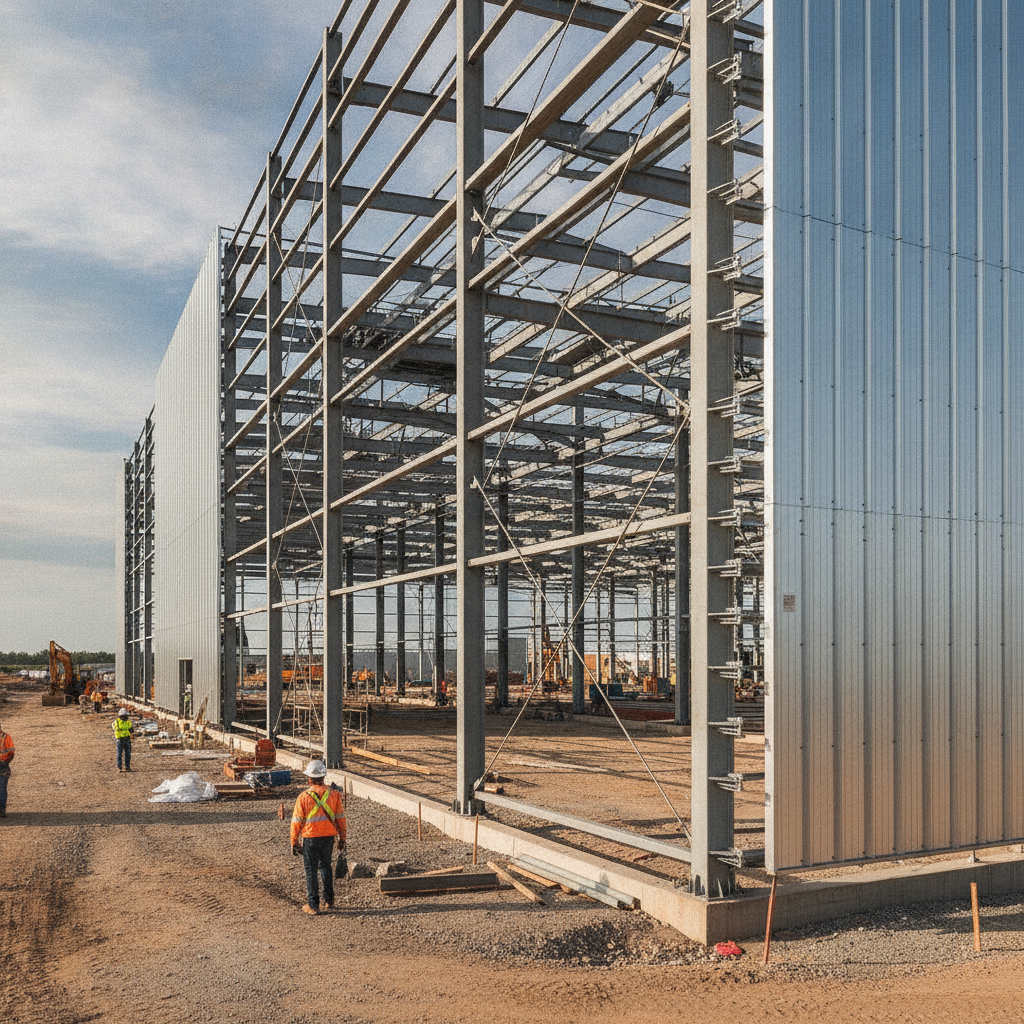
A common point of confusion in wind design is the distinction between the Main Wind Force Resisting System (MWFRS) and Components and Cladding (C&C). The MWFRS is the primary structural frame that provides the overall stability of the building—items like moment frames, braced frames, shear walls, and roof diaphragms. It is designed to resist the total wind load acting on the entire structure. In contrast, C&C refers to the elements that form the building envelope and do not contribute to the overall stability of the structure. This includes wall panels, roofing membranes, windows, louvers, and the fasteners that connect them to the structural frame. Wind pressures on C&C can be significantly higher and more localized than the pressures on the MWFRS, especially at corners, roof edges, and ridges where wind flow creates intense suction. A failure of a C&C element, such as a piece of roofing peeling off, can lead to water intrusion and a progressive failure of the building envelope, even if the main structure remains intact. Therefore, a successful design requires meticulous coordination of the load path from the cladding, through its fasteners, and into the MWFRS.
Mitigating Critical Risks: Roof Uplift and Parapet Effects
The roof is often the most vulnerable part of a building during a high-wind event. As wind flows over the roof, it creates a pressure differential that results in a significant upward force, known as wind uplift. This force is most extreme at the corners and perimeter of the roof. If the roof system and its anchorage are not designed to resist these peak uplift pressures, a failure can occur, leading to immediate and severe water damage to the sensitive equipment below. Parapets, while common in data center design, complicate the aerodynamic profile of the roof. They can increase the uplift pressures on the roof membrane, particularly near the perimeter. The design must account for these amplified loads through robust fastener specification, proper membrane adhesion, and secure flashing details. The parapet design itself must also be robust, as it is subjected to high direct wind pressures. A comprehensive analysis by a qualified Professional Engineer is essential to address these complex aerodynamic effects and ensure the entire roofing assembly performs as a single, integrated system.
Securing Rooftop and Ground-Mounted Equipment Against Wind Loads
Data centers rely on a vast array of heavy and expensive equipment, much of which is located on the roof or in an adjacent equipment yard. This includes cooling towers, chillers, air handling units, and backup generators. Each piece of rooftop equipment presents a significant surface area to the wind and must be securely anchored to prevent it from sliding, overturning, or becoming airborne debris. The anchorage design is a critical structural engineering task that must transfer the calculated wind loading from the equipment, through its supports, and into the building’s main structural frame. This process requires close utility coordination between mechanical, electrical, and structural engineers early in the site development phase. The structural system must be designed to accommodate the concentrated loads from these units, and the anchorage details must be specified precisely. This includes considerations for curb design, dunnage steel, and the specific bolts or welds used to make the connection. Neglecting these details can lead to catastrophic equipment failure and compromise the integrity of the roof system.
Protecting the Building Envelope from Wind-Borne Debris
In many parts of the country prone to severe windstorms, the impact from wind-borne debris is a primary cause of building failure. A projectile striking a window, louver, or wall panel can create an opening in the building envelope. This breach allows the high-pressure wind to enter the building, dramatically increasing the internal pressure and the net uplift force on the roof, which can lead to a complete structural collapse. For a mission-critical facility, maintaining a sealed envelope is paramount. To counter this threat, building codes in vulnerable regions mandate opening protection. This is achieved by using impact-resistant systems, such as laminated glazing or storm shutters for windows, and specifying wall and louver systems that have been tested to withstand specific debris impacts. The entire building envelope, including doors, vents, and other penetrations, must be designed as a hardened, continuous barrier. This level of impact resistance is a fundamental component of a resilient design strategy for any data center located in a high-risk area.
Designing Beyond Minimum Code for Ultimate Uptime
For data center owners, the governing building code should be viewed as the absolute minimum standard for life safety, not the optimal standard for operational continuity. A facility can meet 100% of building code compliance requirements and still suffer damage in a severe storm that leads to extended downtime. True resilience often requires a performance-based approach that goes beyond these minimums. Methods for achieving enhanced resilience include designing the facility for a higher Risk Category than required, using a design wind speed associated with a longer mean recurrence interval (MRI), or specifying C&C systems with pressure ratings well above the calculated design loads. For particularly complex or high-value facilities, physical wind tunnel testing on a scale model can provide a much more accurate understanding of site-specific wind pressures than analytical methods alone. This investment in a performance-based design can significantly reduce the risk of business interruption and protect critical infrastructure.
Our Process: An Integrated Approach to Wind-Resistant Design
At RSP Engineers, we believe a resilient structure is the result of a proactive and integrated design process. Our approach begins during the initial site development and feasibility stages, where we work with clients to understand their risk tolerance and uptime requirements. Our civil engineering team collaborates closely with the project’s Professional Engineer for the structural design, the architect, and MEP consultants from day one. This collaboration ensures that wind-resistant features are seamlessly integrated into the overall design, from the foundation to the roof. We focus on creating a complete and unambiguous set of construction documents to support clear permit submittals and reduce ambiguity during bidding. During construction, our Construction Management Services team provides oversight to verify that critical details, such as cladding attachment and equipment anchorage, are executed exactly as specified in the design, ensuring the final product meets the intended level of resilience.
Common Pitfalls in Data Center Wind Design
Even with a well-defined code, errors in design and construction can compromise a facility’s ability to withstand high winds. Some common pitfalls include: Underestimating C&C Pressures: Focusing on the main frame while neglecting the much higher, localized pressures on cladding, especially at corners and roof edges. Poor Equipment Anchorage Details: Specifying the need for anchorage but failing to provide specific, engineered details for how the loads are transferred to the structure. Value Engineering the Envelope: Substituting specified roofing or wall panel systems with cheaper alternatives that lack the required wind performance ratings. Lack of Construction Oversight: Improper fastener type, spacing, or installation can completely negate a well-engineered cladding design. Ignoring Projectile Hazards: Failing to secure loose materials and ancillary site equipment that can become wind-borne debris during a storm.
Partner with RSP Engineers for Resilient Mission-Critical Facilities
Designing a data center that can withstand extreme weather requires a specialized skill set and a holistic, proactive approach. The team at RSP Engineers has extensive experience in the complex challenges of mission-critical site development. We provide the expert civil engineering and project coordination needed to navigate complex structural requirements, agency reviews, and the permitting process. We partner with you to ensure your facility is not just code-compliant, but truly resilient.
Conclusion: Fortifying Digital Infrastructure Against Extreme Weather
In conclusion, the wind design of a data center is a complex, multi-disciplinary effort that is fundamental to ensuring its long-term viability and uptime. A successful design goes beyond simply meeting minimum codes; it involves a deep understanding of Risk Category implications, the critical differences between MWFRS and C&C, and the specific vulnerabilities of the building envelope and rooftop equipment. By investing in an enhanced, resilience-focused structural design from the outset, developers and operators can safeguard their critical assets and maintain operational continuity in the face of extreme weather events.
FAQs
-
The Main Wind Force Resisting System (MWFRS) is the primary structural skeleton (e. g. , frames, braces) that resists overall wind loads. Components and Cladding (C&C) are the exterior skin (e. g. , wall panels, roofing) which resist higher, localized wind pressures and transfer them to the MWFRS.
-
Data centers are often classified as Risk Category III or IV because their failure could have severe economic consequences, disrupt public services, or impact national security. This higher category mandates a more robust structural design to ensure a lower probability of failure.
-
Yes, significantly. A building on a hill, escarpment, or exposed plain will experience higher wind speeds than a building in a sheltered valley. Standards like ASCE 7 provide topographic factors that must be applied to the design wind speed to account for these effects.