
Roof Framing for Data Center Mechanical Equipment
A technical guide to roof framing for heavy data center mechanical equipment. Learn about load paths, deflection limits, ponding, and future-proofing from the experts at RSP Engineers.
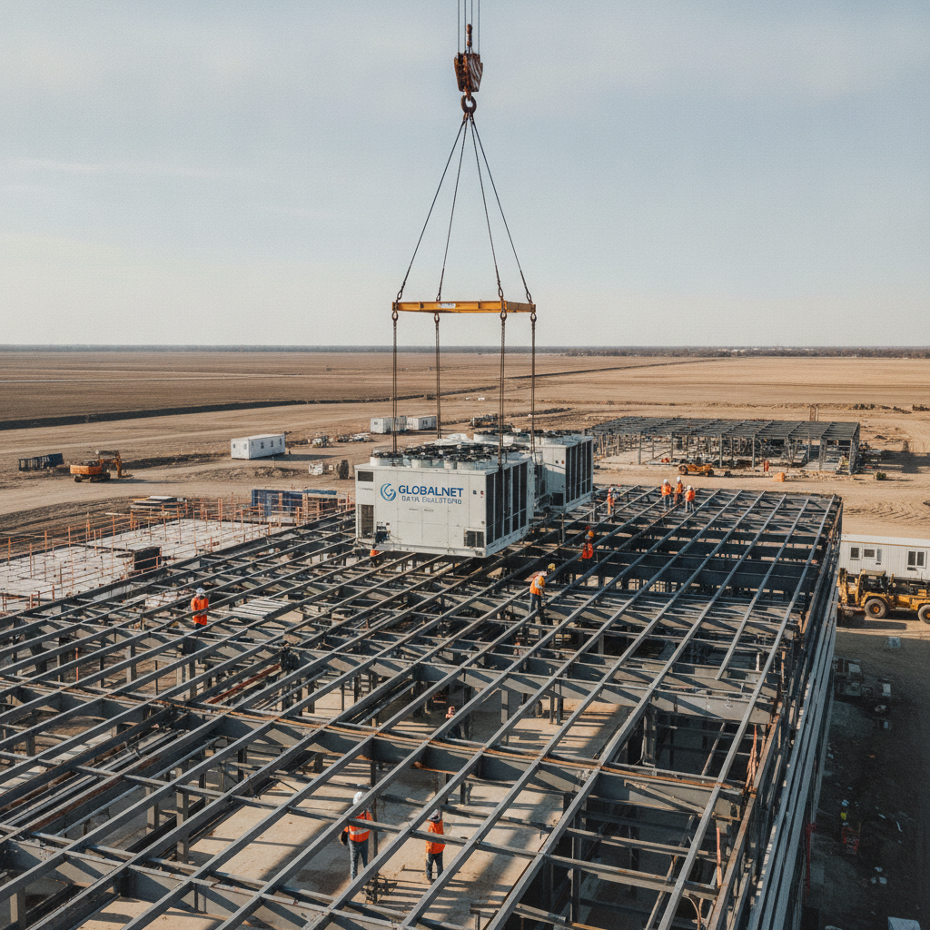
Aligning Equipment with Primary Structural Framing
The fundamental principle of supporting heavy rooftop equipment is to ensure loads are transferred as directly as possible to the primary building structure. This means strategically locating multi-ton units directly over main structural elements like girders, trusses, and the columns that support them. Placing heavy equipment mid-span on secondary members like joists or purlins creates excessive stress, deflection, and is a recipe for structural problems. The goal is to establish a clear and efficient load path from the equipment, through the framing, down the columns, and into the foundation. Achieving this alignment requires intensive, early-stage coordination between the structural engineer, mechanical engineer, and architect. The mechanical equipment layout must inform the structural grid, and vice-versa. This collaborative process, often managed within a Building Information Modeling (BIM) environment, prevents costly redesigns and ensures the structural system is optimized for its intended purpose. Furthermore, the logistics of the overall site development plan must be considered, as crane placement for lifting and setting the equipment is a major factor in determining the final layout.
Concentrated Loads and Point Load Reinforcement
Key Structural Design Considerations for Rooftop Mechanical Units
| Design Factor | Typical Commercial Building | Data Center / Mission-Critical Facility |
|---|---|---|
| Primary Load Type | Uniform live/snow loads | Heavy, concentrated static and dynamic equipment loads |
| Deflection Limits | Standard code limits (e.g., L/240) | Strict limits to protect roofing and equipment (e.g., L/360 or stricter) |
| Vibration Control | Minimal, often for occupant comfort | Critical; requires engineered isolation systems to protect equipment |
| Future Capacity Allowance | Rarely considered | Often designed with a 15-25% load margin for future upgrades |
| Maintenance Live Load | Standard uniform load (e.g., 20 psf) | Higher loads, plus specific analysis for walkways and service areas |
| Ponding/Drift Analysis | Standard analysis | Intensive analysis required due to numerous large obstructions |
Rooftop mechanical units do not apply uniform loads; they transfer their weight through specific support points, creating highly concentrated loads on the structural framing. These point loads, transmitted through equipment curbs or steel dunnage, require localized reinforcement to prevent overstressing the primary members. The structural design must go beyond standard uniform roof loads and analyze these specific points of high stress. Common reinforcement strategies include specifying heavier beams or girders in equipment zones, adding supplementary beams or joists directly beneath support points, and incorporating web stiffeners or bearing plates to distribute the load safely. For complex configurations, a Professional Engineer may use Finite Element Analysis (FEA) to model stress concentrations with high accuracy. This detailed analysis is a critical part of the design process and is verified during construction administration through rigorous inspections to ensure all specified reinforcement is installed correctly before the equipment is loaded onto the roof.
Managing Deflection and Vibration for Equipment Integrity
Beyond simple strength, controlling deflection—the degree to which a structural member bends under load—is paramount. Excessive deflection can damage roofing membranes, leading to leaks that threaten the sensitive equipment below. It can also misalign the shafts and bearings of rotating equipment like fans and pumps, causing premature wear and failure. Similarly, pipe and duct connections are vulnerable to breakage if the supporting structure flexes too much. For these reasons, building code compliance for data centers often involves deflection limits that are significantly stricter than for typical commercial buildings. Structural design criteria, including specific deflection limits and live load requirements, vary by jurisdiction and are dictated by the project’s adopted building codes. Every project team must confirm the applicable standards with the local, state, regional, and federal authorities that hold review authority over the site. Additionally, the constant operation of fans and compressors introduces vibration into the structure. The design must incorporate vibration isolation systems, such as spring isolators or neoprene pads, to dampen these forces and prevent them from propagating through the building and interfering with sensitive operations.
Addressing Drift, Snow Loads, and Water Ponding
The presence of large equipment on a roof alters how environmental loads like snow and rain are handled. Rooftop units act as obstructions, causing snow to accumulate in drifts, creating significant, unbalanced loads that must be accounted for in the structural design per codes like ASCE 7. The weight of this drifted snow can be several times that of the uniform snow load on the rest of the roof, requiring targeted strengthening of the supporting members in those areas. Similarly, the immense weight of mechanical equipment can cause localized depressions in the roof surface. This creates a risk of water ponding, where rainwater accumulates instead of draining. This collected water adds a significant and unplanned dead load, which can cause further deflection, leading to more ponding in a dangerous cycle that can potentially result in a progressive collapse. A robust design integrates the structural analysis with the roof’s drainage design, ensuring positive slope to drains is maintained even after the structure deflects under full load.
Planning for Access, Maintenance, and Safety
A data center roof is a workspace. The structural design must account for the live loads associated with maintenance personnel, tools, and replacement parts. This includes designing permanent walkways, access platforms, and equipment service clearances that can safely support these activities throughout the facility’s lifespan. The structure must be robust enough to handle not just the static weight of the equipment but also the dynamic loads of ongoing service operations. Compliance with Occupational Safety and Health Administration (OSHA) standards is mandatory. The design must incorporate permanent fall protection measures, such as guardrails around the roof perimeter and around large equipment, as well as designated tie-off points for personal fall arrest systems. While less common on rooftops, considerations for overall facility accessibility, including potential ADA compliance for routes leading to roof access points, should be part of a holistic design approach. These safety and access provisions are critical for both personnel safety and long-term operational efficiency.
Future-Proofing: Designing for Equipment Replacement and Upgrades
Mechanical equipment has a finite service life and will eventually require replacement. A forward-thinking structural design anticipates this reality. This can involve designing designated soft spots or removable panels in the roof to facilitate crane access for future equipment swaps. It also means planning the structural framing to support the logistics of removing old units and installing new ones without requiring major structural modifications. Furthermore, technology evolves rapidly. Future generations of cooling or power equipment may be heavier or have different dimensions and support requirements. A smart strategy is to design the roof structure with a modest overcapacity, providing a margin for future upgrades. This foresight adds immense long-term value and prevents the facility from becoming structurally obsolete. This lifecycle approach is a hallmark of high-quality site engineering services and protects the owner’s investment for decades to come.
Our Process: Integrated Structural Design at RSP Engineers
At RSP Engineers, we recognize that designing structures for mission-critical facilities demands a proactive and integrated approach. Our process begins with deep collaboration, engaging with the owner, architect, and MEP engineers from day one to align the structural grid with the demanding equipment layout. We leverage advanced 3D modeling and BIM coordination to resolve conflicts before they reach the field, ensuring a seamless integration of all building systems. Our team of experienced Civil Engineers and structural designers uses state-of-the-art analysis software, including FEA, to precisely model complex loads and design efficient, robust reinforcement. We focus on constructability, value engineering, and lifecycle performance, delivering designs that are not only safe and compliant but also optimized for future flexibility. During construction, we provide comprehensive construction administration and inspection services to verify that every structural detail is executed to the highest standard, safeguarding the integrity of the final build.
Common Issues and How to Avoid Them
Even with careful planning, several common issues can arise when designing roof structures for data centers. A primary challenge is late-stage changes to the specified mechanical equipment, which can have a cascading effect on the structural design, forcing costly and time-consuming redesigns. The best mitigation is to finalize and lock in equipment selections as early as possible in the design process. Another frequent problem is inadequate coordination between structural and MEP systems, leading to clashes with large-diameter piping, ductwork, or cable trays. This is best avoided through a rigorous BIM coordination process involving all disciplines. Finally, underestimating maintenance access requirements or failing to properly analyze snow drift and water ponding can lead to long-term operational and safety issues. A holistic design process that considers the building’s full lifecycle, including a thorough drainage design review, is the most effective way to prevent these pitfalls.
Partner with RSP Engineers for Your Mission-Critical Facility
Designing and engineering the complex structures required for data centers and other mission-critical facilities demands specialized expertise. The team at RSP Engineers brings decades of experience to every project, ensuring your facility’s structural system is resilient, efficient, and built for the future. From initial site plan design and structural analysis to navigating complex permitting processes and providing detailed Construction Management Services, we are your trusted partner. Don’t leave the backbone of your facility to chance.
Conclusion
The roof framing of a data center is a high-performance system integral to the facility’s success. It requires a sophisticated engineering approach that balances immense loads, controls deflection and vibration, and plans for the entire operational lifecycle. Proper load path management, detailed analysis of concentrated forces, and seamless integration with other building systems are non-negotiable. By prioritizing robust structural integrity and adhering to stringent building code compliance, developers and owners can ensure the safety, reliability, and long-term value of their mission-critical investment.
FAQs
-
The structural engineer should be involved from the conceptual or schematic design phase. Early involvement is critical to establish a structural grid that efficiently supports the heavy mechanical equipment, which in turn influences the architectural layout and overall project budget.
-
A late-stage change in equipment can necessitate significant structural redesign. If the new unit is heavier, has a different footprint, or different support points, the supporting beams, joists, and even columns may need to be resized. This underscores the importance of finalizing equipment choices early to avoid impacts on schedule and cost.
-
Rooftop equipment is analyzed for seismic and wind loads according to building codes like ASCE 7. The equipment’s weight, height, and shape are used to calculate these lateral forces. The structural design must include robust anchorage to transfer these forces into the building’s main structure, and the supporting members must be designed to resist the combined effects of gravity, wind, and seismic loads.