
Foundation Design for Modular Data Center Units
A technical guide to foundation design for modular and containerized data centers, covering geotechnical analysis, pier vs. slab systems, utility coordination, and seismic/wind anchorage.
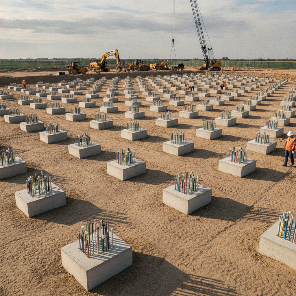
The Critical Role of Precision in Modular Foundation Systems
In modular construction, the mantra is “measure twice, pour once.” The modules are manufactured in a controlled factory environment to exacting tolerances, often within fractions of an inch. The site-built foundation must mirror this precision. The most critical parameters are elevation and levelness across all module support points. An uneven foundation can prevent modules from seating correctly, compromise weatherproof seals between units, and create stress on the module’s structural frame. This can also misalign internal and external electrical busways, cooling pipes, and fiber optic connections, jeopardizing the entire installation. The structural design must account for the unique load paths of modular units. Loads are typically not distributed uniformly but are concentrated at specific point loads, usually at the corners or designated support locations on the module’s steel chassis. The foundation system, whether it’s a slab or a pier-based system, must be engineered to transfer these concentrated loads safely into the underlying soil without differential settlement. This requires close collaboration between the civil engineering team, the structural engineer, and the module manufacturer to ensure the foundation design is based on the exact specifications of the units being deployed.
Geotechnical Investigation and Site Preparation
Foundation System Comparison for Modular Data Centers
| Feature | Slab-on-Grade Foundation | Pier and Grade Beam System |
|---|---|---|
| Load Distribution | Distributes loads over a wide area; best for uniform loading. | Ideal for concentrated point loads at module corners and support points. |
| Utility Integration | Utilities are embedded within or routed around the slab. Less accessible for maintenance. | Creates a crawl space, allowing for easy routing, access, and maintenance of utilities. |
| Suitability for Poor Soils | Less suitable; requires extensive soil improvement or becomes prohibitively thick. | Highly suitable; piers can be extended to reach stable bearing soil strata. |
| Tolerance & Precision | Achieving extreme flatness over a large area can be challenging. | Precision is focused on individual pier locations and elevations, which can be easier to control. |
| Cost Profile | Generally lower initial material and labor cost on sites with good soil. | Higher initial cost but offers greater design flexibility and long-term access benefits. |
| Phased Expansion | Can be expanded, but requires careful construction joint planning. | Excellent for phased build-outs; new piers can be added with less disruption. |
Every successful foundation design begins below the surface with a comprehensive Geotechnical soil report. This investigation, conducted by a qualified Geotechnical engineer, analyzes soil composition, bearing capacity, settlement potential, and the presence of groundwater. The findings from the Soil boring test and laboratory analysis directly inform the type, depth, and design of the foundation system. For example, sites with low-bearing-capacity soils may require deep foundations like drilled piers, while sites with stable, strong soils might be suitable for a slab-on-grade solution. Once the geotechnical conditions are understood, meticulous site preparation is essential. This involves grading the site to achieve the required elevations and drainage patterns, and compacting the subgrade to provide a stable base for the foundation. Proper stormwater management and drainage design are integrated at this stage to prevent water infiltration and protect the foundation’s integrity over the long term. It is crucial to understand that earthwork, grading, and permitting requirements vary by jurisdiction, and every project team should confirm the applicable standards with the local, state, regional, and federal authorities that hold review authority over the site. This ensures full zoning compliance and avoids regulatory hurdles during construction.
Comparing Foundation Types: Slab-on-Grade vs. Pier and Grade Beam
The choice between a monolithic slab and a pier-based system depends on geotechnical conditions, module specifications, and project requirements. Each approach has distinct advantages and is suited to different scenarios. The decision is a critical part of the initial site plan design and has long-term implications for cost, schedule, and future expansion. Slab-on-Grade Foundations A slab-on-grade foundation consists of a single, thick layer of reinforced concrete poured directly on a prepared subgrade. This option is often considered for sites with excellent soil conditions and for modules that impart relatively uniform loads. The design must incorporate adequate reinforcement (rebar or mesh) to control cracking and manage thermal expansion and contraction. For data centers, the slab must be exceptionally flat and level to meet the module manufacturer’s specifications. While seemingly simple, a high-tolerance slab requires expert execution and rigorous quality control during the pour. Pier and Grade Beam Systems A pier and grade beam system is frequently the preferred solution for modular data centers. This design uses concrete piers (or columns) installed at each module support point to carry the concentrated point loads. These piers are connected by reinforced concrete “grade beams” that provide lateral stability and create a rigid structural grid. This system is highly adaptable to sites with variable or poor soil conditions, as piers can be extended to deeper, more stable soil layers. A key advantage is the crawl space created beneath the modules, which provides an accessible and protected zone for running utilities, simplifying both initial installation and future maintenance.
Key Design Considerations for Foundation Systems
Beyond the primary choice of foundation type, several other critical factors must be engineered with precision. These elements require tight coordination among all design disciplines, including civil, structural, mechanical, and electrical engineering, as well as the module vendor and the general contractor. Anchorage for Wind and Seismic Forces Modular units, despite their weight, present a large surface area and must be securely anchored to the foundation to resist lateral forces from wind and seismic events. The structural design must comply with the project’s adopted building code compliance requirements, often referencing national standards like ASCE 7. This involves calculating the potential uplift and shear forces and designing an anchorage system—typically using embedded anchor bolts or welded plates—that can safely transfer these loads into the foundation and surrounding soil. The manufacturer’s specifications for anchorage points and load capacities are non-negotiable inputs for this design. Utility Stub-Up and Penetration Coordination Accuracy is paramount when locating utility penetrations. Electrical conduits, cooling pipes, and fiber optic ducts must stub up from the foundation at precise locations to align perfectly with the connection points on the underside of the module. An error of even an inch can necessitate costly and time-consuming rework, such as core drilling through a newly poured foundation. Effective utility coordination, often managed through integrated 3D modeling (BIM), is essential. The civil engineering team must work from the manufacturer’s approved shop drawings to create a foundation plan that guarantees perfect alignment. Designing for Phased Expansion Data center campuses are rarely built to their final capacity on day one. A common strategy is to deploy modules in phases as demand grows. The initial site development and foundation design must anticipate this future growth. This means planning the layout of the entire “foundation field,” including reserving space for future modules, and pre-installing underground utility corridors and access pathways. Designing the initial phase with expansion in mind ensures that future additions can be completed with minimal disruption to live data center operations, protecting uptime and revenue.
The RSP Engineers Design and Coordination Process
At RSP Engineers, our approach to modular data center foundations is built on a process of rigorous analysis and proactive coordination. We begin by commissioning and interpreting the Geotechnical soil report to establish a baseline for design. Our team then engages directly with the module manufacturer to obtain the exact structural loads, support locations, anchorage details, and utility connection points. This critical data is integrated into our site plan design from day one. We utilize Building Information Modeling (BIM) to create a unified 3D model that overlays the foundation, utilities, and module geometry. This allows us to detect and resolve clashes before construction begins, ensuring that every anchor bolt and conduit is placed with absolute precision. Throughout the construction administration phase, we provide oversight and quality control, working with the contractor to verify elevations, locations, and tolerances, ensuring the final product perfectly matches the design intent and is ready for a seamless module installation.
Common Issues and Mitigation Strategies in Foundation Construction
Even with a robust design, challenges can arise during construction. Common issues include incorrectly set anchor bolts, out-of-tolerance pier elevations, and misaligned utility stub-ups. These errors can often be traced back to a breakdown in communication or a lack of specialized quality control. Another significant risk is differential settlement, where parts of the foundation settle more than others, which can be catastrophic for interconnected modules. Mitigation starts with a detailed set of construction documents that leave no room for ambiguity. We recommend the use of steel templates to ensure precise anchor bolt patterns. A stringent quality assurance plan, including regular verification surveys by a licensed surveyor at critical stages, is essential. Clear communication protocols between the general contractor, concrete subcontractor, surveyors, and the civil engineering team are vital. For settlement risk, a well-executed geotechnical investigation and adherence to its recommendations are the best defense.
Partner with RSP Engineers for Your Mission-Critical Facility
The success of your modular data center project rests on the precision and reliability of its foundation. At RSP Engineers, we provide the expert civil engineering, detailed site plan design, and meticulous utility coordination required for these demanding projects. Our team understands the unique interface between site construction and prefabricated modules. We manage the complexities of permitting, geotechnical analysis, and structural integration to deliver a foundation that meets the exacting tolerances your mission-critical facility demands. Contact us to ensure your project is built on a solid footing from day one.
Conclusion: A Foundation for Digital Infrastructure
Designing a foundation for a modular data center is a specialized discipline that blends the principles of civil engineering, structural design, and manufacturing logistics. Success hinges on precision, proactive coordination with the module vendor, and a deep understanding of the site’s geotechnical characteristics. By prioritizing these elements, developers can mitigate risks and ensure a smooth, efficient installation. A well-engineered foundation is more than just concrete and steel; it is the critical enabling platform for a scalable, reliable, and resilient digital future, making experienced civil engineers an indispensable part of any data center development team.
FAQs
-
They are absolutely critical. Modular units are built to precise factory dimensions. A foundation that is not perfectly level or has incorrect elevations can prevent the module from seating, compromise weather seals, and misalign critical power and cooling connections, leading to significant rework and delays.
-
The Geotechnical engineer is essential. They perform the subsurface investigation, including the Soil boring test, to determine the soil’s capacity to support the heavy, concentrated loads of the data center modules. Their Geotechnical soil report provides the foundational data needed by the structural and civil engineers to design a safe and stable foundation system that will not settle over time.
-
It is possible but requires careful evaluation. An engineering assessment must be performed to confirm the existing slab’s thickness, reinforcement, and load-bearing capacity. A geotechnical analysis is also needed to ensure the underlying soil can support the new, concentrated point loads. Often, significant modifications or a new, purpose-built foundation are required.