
Establishing Utility Corridors Across Data Center Campuses
Learn the civil engineering principles for establishing utility corridors on data center campuses, including duct bank consolidation, separation standards, easement planning, and future-proofing missi
The Strategic Importance of Master Utility Planning
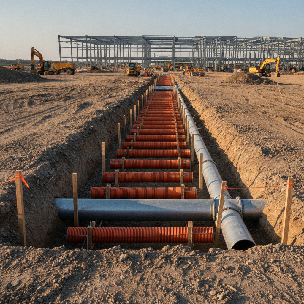
For a mission-critical facility, an ad-hoc approach to utility placement is a recipe for disaster. Simply running conduits and pipes along the shortest path creates a tangled, unmanageable web that hinders future growth and complicates repairs. A comprehensive master plan, developed during the initial phases of site development, is essential. This plan treats the utility network as a primary organizing element of the campus, second only to the data hall buildings themselves. This proactive approach ensures that all infrastructure is logically organized to support day-one requirements and decades of future expansion. Effective master planning involves forecasting ultimate campus build-out to size corridors for future capacity, not just immediate needs. It establishes clear rules for utility coordination, ensuring that electrical, mechanical, and communications systems can coexist without interference. By defining these pathways early, developers can optimize the overall site plan design, preserve valuable land for revenue-generating buildings, and provide clear, safe access for maintenance crews. This level of foresight is what separates a functional site from a high-performance, resilient data center campus.
Defining the Corridor: Easements and Right-of-Way
Key Utility Corridor Separation Standards
| Utility Relationship | Typical Horizontal Separation | Typical Vertical Separation (at Crossing) | Key Design Considerations |
|---|---|---|---|
| High-Voltage Electrical vs. Communications/Fiber | 5-10 feet | 1-3 feet | Prevent electromagnetic interference (EMI). Maximize separation where possible. Use of shielding conduit may be required. |
| Electrical vs. Water/Sewer | 10 feet | 2 feet | Ensure electrical infrastructure is protected from potential leaks. Facilitate safe excavation and repair access for either utility. |
| Potable Water vs. Sanitary Sewer | 10 feet | 1.5 feet (Water Over Sewer) | Critical for public health. Water lines must always cross over sewer lines to prevent contamination in case of a pipe failure. |
| Chilled Water Lines vs. Other Utilities | 3-5 feet | 1 foot | Insulated pipes require significant space. Access for valve and joint maintenance is critical. Avoid placing directly over sensitive fiber. |
| Redundant Fiber Routes | 20+ feet | N/A (Parallel) | The goal is maximum physical diversity. Routes should be in separate trenches, and ideally on opposite sides of the corridor or site. |
A utility corridor is more than just a trench; it is a legally defined space protected by easements and rights-of-way. These legal instruments are critical for guaranteeing long-term access for installation, maintenance, and future upgrades. The civil engineering process begins with a thorough title review and survey to identify existing encumbrances and establish new, dedicated utility easements for the campus infrastructure. The width of these easements is a critical design decision, calculated to accommodate not only the physical footprint of the utilities but also the construction equipment needed to install them and the separation required between them. Sizing these corridors requires a deep understanding of the project’s lifecycle. An easement designed only for the initial phase of development can become a major bottleneck, forcing expensive and disruptive relocations later. A well-defined corridor plan, recorded as part of the formal land development process, provides certainty for investors, operators, and utility providers. It ensures that the pathways for power, water, and data remain clear and unobstructed by future buildings, parking lots, or stormwater management facilities.
Consolidating High-Capacity Electrical Duct Banks
The defining feature of any data center utility corridor is the massive network of electrical duct banks. These are not single conduits but vast, concrete-encased arrays carrying medium-voltage power from the utility substation to the facility’s transformers. The design of these duct banks is a complex discipline involving thermal analysis to prevent overheating, structural design to support overlying loads, and meticulous utility coordination with the power company. Consolidating these pathways into a primary corridor simplifies routing and protects the most critical utility on campus. The routing must avoid sharp bends that make cable pulling difficult and must maintain specified depths to protect the infrastructure. The design must also account for the sheer scale and weight, ensuring that the underlying soils can support the load without settlement. A Professional Engineer specializing in site-civil design works closely with electrical engineers and geotechnical experts to ensure the duct bank system is both robust and constructible, forming the reliable power backbone of the entire campus.
Integrating Water, Sewer, and Fiber Optic Infrastructure
While power is paramount, other utilities are equally vital. Modern data centers often rely on chilled water loops for cooling, requiring large-diameter supply and return pipes. These process water systems must be routed with precision to minimize pumping distances and pressure loss. Alongside them run domestic water lines for office and support areas and sanitary sewer systems, which may include lift stations and force mains on large, relatively flat sites. Equally important are the redundant fiber optic pathways. To ensure uptime, data centers require multiple, physically separate (or ‘diverse’) fiber routes connecting to different carriers. The utility corridor provides a protected and organized path for this critical infrastructure. The civil engineering design must ensure these sensitive cables are not laid too close to high-voltage power lines to prevent electromagnetic interference (EMI) and are accessible for future upgrades or repairs without disrupting other essential services.
Critical Separation and Crossing Standards
Utilities cannot be placed arbitrarily within a corridor. A clear set of rules governing horizontal and vertical separation is essential to prevent conflicts and ensure safety. For example, high-voltage electrical lines must be kept a safe distance from communications cables to prevent interference. Water mains must be located horizontally and vertically separate from sewer lines to prevent cross-contamination in the event of a leak. These separation standards are dictated by a combination of national codes, utility provider requirements, and sound engineering judgment. Detailed cross-section drawings are a key component of the permit submittals, demonstrating to reviewers that all separation requirements have been met. Permitting requirements for utility installation vary by jurisdiction, and every project team should confirm the applicable standards with the local, state, regional, and federal authorities that hold review authority over the site. Proper conflict analysis, often aided by 3D modeling, is performed during the design phase to identify and resolve any potential clashes before construction begins, saving significant time and money.
Coordination with Stormwater Management and Site Layout
A utility corridor does not exist in a vacuum. It must be carefully integrated with the overall campus layout, including building footprints, roadways, and, critically, the stormwater management system. The corridor’s alignment must avoid proposed retention or detention ponds, underground infiltration systems, and major drainage swales. The grading of the corridor itself must be coordinated with the site’s overall drainage design to prevent erosion or the ponding of water over critical infrastructure. This integration is a core task of the civil engineering team. By mapping all site constraints early in the process, engineers can establish a corridor alignment that avoids conflicts. This prevents scenarios where a utility trench undermines a future building foundation or where a stormwater pond must be relocated at great expense because it was placed over the primary electrical duct bank path. This holistic view ensures all elements of the site development plan work in harmony.
RSP’s Approach to Utility Corridor Master Planning
At RSP Engineers, our process begins with a comprehensive due diligence and feasibility study. We work with data center developers to understand their ultimate vision for the campus, including phasing, power density, and cooling strategies. Our team of Civil Engineers then develops a master utility plan that serves as a roadmap for all subsequent design and construction. This involves close collaboration with utility providers to confirm service capacities and routing requirements. We utilize 3D modeling to visualize the entire subsurface environment, running conflict analysis to de-risk the construction phase. Our plans prioritize not just installation but also long-term maintenance and future expansion, ensuring that access is preserved and new utilities can be added without disrupting ongoing operations. From initial concept through final agency review and construction administration, we provide the expert guidance needed to deliver a resilient and scalable utility backbone for mission-critical facilities.
Common Issues in Data Center Utility Design
Even with careful planning, challenges can arise. Some of the most common issues we help clients avoid include: Underestimating Future Capacity: Sizing easements and conduits only for Phase 1 can severely constrain future growth. We always plan for the ultimate build-out. Ignoring Geotechnical Conditions: Poor soil conditions, rock, or a high water table can dramatically increase the cost of trenching and duct bank installation. A thorough Geotechnical Engineering investigation is non-negotiable. Discovering Utility Conflicts in the Field: Inadequate subsurface investigation or 2D-only design can lead to costly delays when an unknown pipe or conduit is struck during excavation. Neglecting Maintenance Access: Placing utilities under permanent structures or without sufficient clearance for repair equipment can turn a minor issue into a major shutdown. Poor As-Built Documentation: Failing to accurately document the final, installed location of all utilities creates significant risks for any future excavation or site work.
Your Partner in Mission-Critical Site Development
Establishing a robust utility corridor is a complex undertaking that requires a multidisciplinary approach and deep expertise in site development. The team at RSP Engineers has the experience to guide your project from initial feasibility and master planning through permitting and construction. If you are planning a data center campus, contact us today to discuss how our site engineering services and strategic approach to utility coordination can help ensure your project’s success.
Conclusion
The utility corridor is the unsung hero of the data center campus. While the data halls get the attention, it is this carefully planned network of underground infrastructure that guarantees the reliability, scalability, and long-term viability of the entire operation. Strategic civil engineering, proactive utility coordination, and a forward-looking master plan are not expenses—they are essential investments in the foundation of your mission-critical facility. Partnering with experienced Civil Engineering firms ensures this foundation is solid.
FAQs
-
The width varies based on the ultimate scale of the campus, but primary corridors are often 50 to 100 feet wide. This accommodates multiple, large-scale electrical duct banks, large-diameter water lines, sewer, and redundant fiber, all while maintaining required horizontal separations and providing space for construction and maintenance equipment.
-
A 3D model is an invaluable tool for utility coordination and clash detection. It allows designers to visualize the complex underground environment, ensuring that pipes and conduits maintain proper vertical and horizontal separation. This proactive conflict analysis prevents costly and time-consuming surprises during construction.
-
We incorporate flexibility into the master plan. This includes reserving space within the utility corridor for future conduits (‘spare conduits’), oversizing easements to accommodate additional infrastructure, and documenting the location of all existing utilities with precise as-built surveys to simplify future design work.