
Dynamic Analysis of Data Center Equipment Foundations
Explore the principles of dynamic analysis for data center equipment foundations. Learn about resonance, soil-structure interaction, and vibration limits for mission-critical facilities.
Distinguishing Static vs. Dynamic Loads in Mission-Critical Facilities
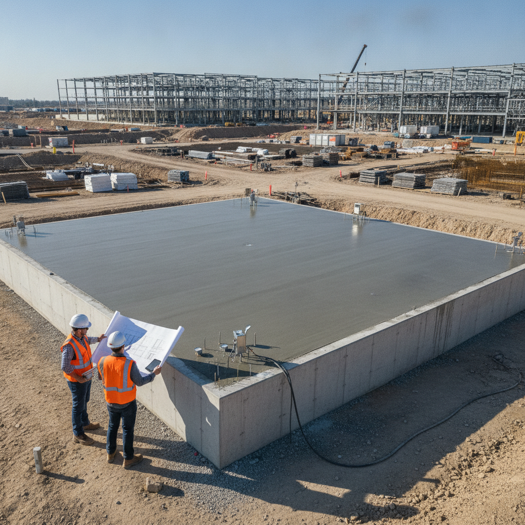
A foundational concept in structural engineering is the distinction between static and dynamic loads. Static loads are forces that are applied slowly and remain relatively constant over time. These include the self-weight of the structure (dead load), the weight of occupants and furniture (live load), and environmental forces like snow. Traditional foundation design focuses on ensuring the soil has adequate bearing capacity to support these loads without excessive settlement. The analysis assumes a state of equilibrium where forces are balanced. Dynamic loads, in contrast, are time-varying forces that cause a structure to vibrate. In a data center, this primarily involves forces generated by heavy rotating or reciprocating machinery like diesel generators, large chillers, and industrial pumps. These machines create cyclical, unbalanced forces during operation. A dynamic analysis does not assume equilibrium; instead, it evaluates the system’s response to these vibrations, considering factors like frequency, amplitude, and damping. Ignoring these dynamic effects and using a simplified static design can lead to severe operational issues and long-term damage.
Characterizing Machine-Induced Forces and Frequencies
Dynamic Analysis Approaches: Simplified vs. Detailed
| Parameter | Simplified Method (Rules of Thumb) | Detailed Analysis (Finite Element Method) |
|---|---|---|
| Applicability | Small, non-critical equipment; preliminary sizing; low-vibration machinery. | Large, mission-critical equipment (generators, chillers); high-precision machinery; complex soil conditions. |
| Key Inputs | Equipment weight, basic operating speed (RPM), general soil type. | Certified OEM dynamic load data, detailed Geotechnical soil report with dynamic properties, foundation geometry. |
| Analysis Complexity | Low. Often based on simple mass ratios (e.g., foundation mass = 3-5x machine mass). | High. Requires specialized software to model soil-structure interaction and solve time-history or frequency-response equations. |
| Core Principle | Overwhelm dynamic forces with sheer mass. Aims to create a high-inertia block. | Precisely calculate the foundation's natural frequency and predicted vibration amplitudes to ensure they are within acceptable limits. |
| Output / Deliverable | A preliminary foundation footprint and thickness. | A fully optimized foundation design with predicted vibration amplitudes, verification of frequency separation, and detailed construction drawings. |
| Risk Profile | Higher risk of resonance or excessive vibration if misapplied to sensitive or powerful equipment. | Lower risk. Provides a high degree of confidence in the foundation's performance under all specified operating conditions. |
The first step in any dynamic analysis is to precisely define the forces the machine will exert on its foundation. This information is provided by the Original Equipment Manufacturer (OEM) in a detailed data package. Key parameters include the machine’s operating frequencies (typically given in revolutions per minute or RPM), the magnitude and location of unbalanced forces, and the presence of any significant harmonics. These forces are the primary input that drives the entire analysis and design process. It is critical for the engineering team to obtain a complete and certified data sheet from the OEM. This document specifies the dynamic loads for all operating conditions, including startup, shutdown, and potential fault scenarios. The structural engineer uses this data to model the forcing functions that the foundation must resist. Without accurate OEM data, the analysis would rely on assumptions, introducing significant risk into the site development and design of these critical support structures.
The Critical Role of Soil-Structure Interaction
A foundation does not exist in isolation; it is part of a coupled system with the underlying soil. The response of the foundation to dynamic loads is heavily influenced by the properties of the soil, a concept known as soil-structure interaction. The soil provides stiffness and damping to the system, which affects the foundation’s natural frequency and how quickly vibrations dissipate. A thorough geotechnical investigation is therefore non-negotiable for any dynamic foundation design. The Geotechnical engineer must provide specific dynamic soil properties, which go beyond a standard soil report. These include parameters like the soil’s shear wave velocity, dynamic shear modulus, and Poisson’s ratio. These values help the structural engineer model the soil as a series of springs and dashpots, simulating its stiffness and energy-dissipating (damping) characteristics. Because soil conditions and testing requirements vary by jurisdiction, every project team should confirm the applicable standards with the local, state, regional, and federal authorities that hold review authority over the site. This ensures the Geotechnical soil report provides all necessary data for a robust analysis.
Preventing Resonance: Aligning Foundation and Equipment Frequencies
The central goal of dynamic foundation design is to prevent resonance. Resonance occurs when the operating frequency of the machine is too close to the natural frequency of the foundation-soil system. When this happens, the vibration amplitudes can multiply dramatically, leading to excessive movement, equipment malfunction, and potential structural failure. The design process is an exercise in tuning the foundation’s properties to avoid this critical condition. To achieve this, engineers design the foundation so that its natural frequency is sufficiently separated from the machine’s operating frequency. A common industry rule of thumb is to ensure the foundation’s natural frequency is at least 25% higher (for high-tuned foundations) or 20% lower (for low-tuned foundations) than the machine’s primary operating frequency. This requires careful manipulation of the foundation’s mass and stiffness. For example, a more massive foundation block will generally have a lower natural frequency, while a stiffer foundation geometry will have a higher one. This iterative process of foundation design is key to long-term stability.
Establishing Vibration Amplitude and Velocity Limits
Beyond avoiding resonance, a dynamic analysis must also ensure that the predicted vibration amplitudes and velocities remain within acceptable limits. Even if resonance is avoided, high-amplitude vibrations can still damage sensitive equipment components, cause connections to loosen, or transmit disruptive vibrations to adjacent structures and personnel. These performance criteria are crucial for ensuring the long-term reliability and serviceability of the equipment. Acceptable limits are typically established by two sources: the equipment manufacturer and industry standards (such as those from ASHRAE or the Hydraulic Institute). The OEM specifications are paramount, as operating the equipment outside of these prescribed vibration limits can void the warranty. The structural engineer runs the analysis to calculate the maximum expected displacement, velocity, and acceleration of the foundation and compares these values against the allowable thresholds to confirm building code compliance and operational safety.
Our Process: A Phased Approach to Dynamic Foundation Analysis
At RSP Engineers, we follow a systematic process to deliver robust and reliable foundation designs for dynamic equipment. Our approach ensures all critical variables are considered, from initial data collection through final construction documentation. Data Collection and Review: We begin by coordinating with the project team to secure certified dynamic load data from the equipment manufacturer and commission a specialized geotechnical investigation to determine the site’s dynamic soil properties. Preliminary Sizing and Modeling: Using the collected data, our engineers perform preliminary calculations and develop an initial foundation model. This step often involves simplified methods to establish a baseline design and identify potential challenges early in the process. Detailed Finite Element Analysis (FEA): We then build a detailed computer model of the foundation-soil system. This model incorporates the complex geometry of the foundation, the material properties of concrete and steel, and the dynamic properties of the soil to simulate how the system will respond to the machine’s vibrations. Analysis, Iteration, and Optimization: The model is subjected to the specified dynamic loads. We analyze the results to check for resonance and verify that vibration amplitudes are within OEM limits. The design is iteratively refined—adjusting mass, stiffness, and geometry—until all performance criteria are met. Final Design and Documentation: Once the design is optimized, we produce a complete set of construction documents, including detailed drawings and technical specifications. This ensures the contractor has clear guidance for building the foundation exactly as it was engineered.
Common Issues and Mitigation Strategies
Even with a robust process, challenges can arise in dynamic foundation design. A primary issue is receiving incomplete or non-certified data from equipment manufacturers, which can delay the analysis. We mitigate this by engaging with vendors early and using conservative assumptions until certified data is available. Another common problem is encountering unexpected soil conditions during construction that differ from the geotechnical investigation. This is addressed by having the Geotechnical engineer on call for construction-phase support and developing contingency plans for ground improvement if necessary. Finally, the potential for vibration transmission to adjacent structures is a key concern. We mitigate this through careful site planning and the use of isolation joints to decouple the dynamic foundation from the main building slab.
Partner with RSP Engineers for Your Mission-Critical Foundation Design
Ensuring the stability of your data center’s most critical equipment requires specialized engineering expertise. The team at RSP Engineers has extensive experience in performing detailed dynamic analysis and designing robust foundations for mission-critical facilities nationwide. We provide comprehensive site engineering services, from initial Geotechnical Engineering coordination to final structural design and construction administration. Our integrated approach ensures that your foundations are optimized for performance, reliability, and long-term value.
Conclusion
The foundation beneath a data center’s heavy machinery is far more than a simple concrete slab; it is an engineered system designed to manage complex dynamic forces. A successful design hinges on a deep understanding of soil-structure interaction, precise characterization of machine loads, and a meticulous analysis to prevent resonance. By investing in a proper dynamic analysis, facility owners can protect their critical assets, ensure operational uptime, and avoid the significant costs associated with vibration-related failures. This specialized discipline is a cornerstone of modern mission-critical engineering.
FAQs
-
A static analysis evaluates a foundation’s ability to support constant, unmoving loads, focusing on bearing capacity and settlement. A dynamic analysis evaluates the foundation’s response to time-varying, vibratory loads from machinery, focusing on preventing resonance and limiting vibration amplitude.
-
Standard details are designed for static loads only. A generator produces significant dynamic forces that can cause a standard foundation to vibrate excessively. This can lead to premature equipment failure, damage to connected utilities, and potential structural issues. A custom dynamic foundation design is required to ensure long-term reliability.
-
Beyond standard bearing capacity, the Geotechnical engineer must provide dynamic soil properties. This includes the soil’s shear wave velocity, dynamic shear modulus, Poisson’s ratio, and material damping ratio. This data is essential for accurately modeling the soil-structure interaction.