
Fuel Tank Foundation Design for Data Center Sites
A technical guide to designing fuel tank foundations for data centers. Learn about ring walls vs. slabs, buoyancy resistance, seismic anchorage, and secondary containment from civil engineering expert
Geotechnical Considerations and Site Investigation
Every successful foundation design begins below the ground. Before any concrete is placed, a thorough geotechnical investigation is essential to understand the subsurface conditions that will support the tank. This investigation, summarized in a Geotechnical soil report, provides the critical data needed to engineer a stable and reliable foundation system. Key parameters evaluated include soil bearing capacity, potential for settlement, and the location of the groundwater table. The investigation typically involves performing a series of soil boring tests to collect samples and characterize the soil strata. This data allows the geotechnical engineer to identify weak or compressible soil layers, such as soft clays or loose sands, that could lead to excessive or differential settlement. The report provides recommendations for the allowable soil bearing pressure and informs the selection of the most appropriate foundation type, whether it’s a shallow system like a ring wall or slab, or a deep foundation system involving piles or piers for sites with poor soil conditions.
Ring Wall vs. Full Slab Foundation Systems
Comparison of Fuel Tank Foundation Systems
| Feature | Ring Wall Foundation | Full Slab Foundation |
|---|---|---|
| Primary Application | Vertical cylindrical tanks on sites with high-bearing-capacity, uniform soils. | Tanks on sites with variable or lower-bearing-capacity soils; often used for larger tanks. |
| Soil Condition Suitability | Best for dense, stable granular soils or stiff clays. Not ideal for soft or compressible soils. | Suitable for a wider range of soil conditions, including those prone to differential settlement. |
| Settlement Tolerance | More susceptible to differential settlement, which can stress the tank floor plate. | Provides more rigid support, helping to minimize differential settlement across the tank footprint. |
| Buoyancy Resistance | Offers less inherent resistance to uplift; may require separate ground anchors in high groundwater. | Can be designed with sufficient mass (thicker/wider slab) to provide significant resistance to hydrostatic uplift. |
| Integrated Containment | Containment structure is typically built separately or adjacent to the ring wall. | Easily integrated; the slab serves as the containment floor, with walls tied directly into it. |
| Relative Cost | Generally lower initial cost due to less concrete and reinforcement. | Higher initial cost due to greater material volume and labor. |
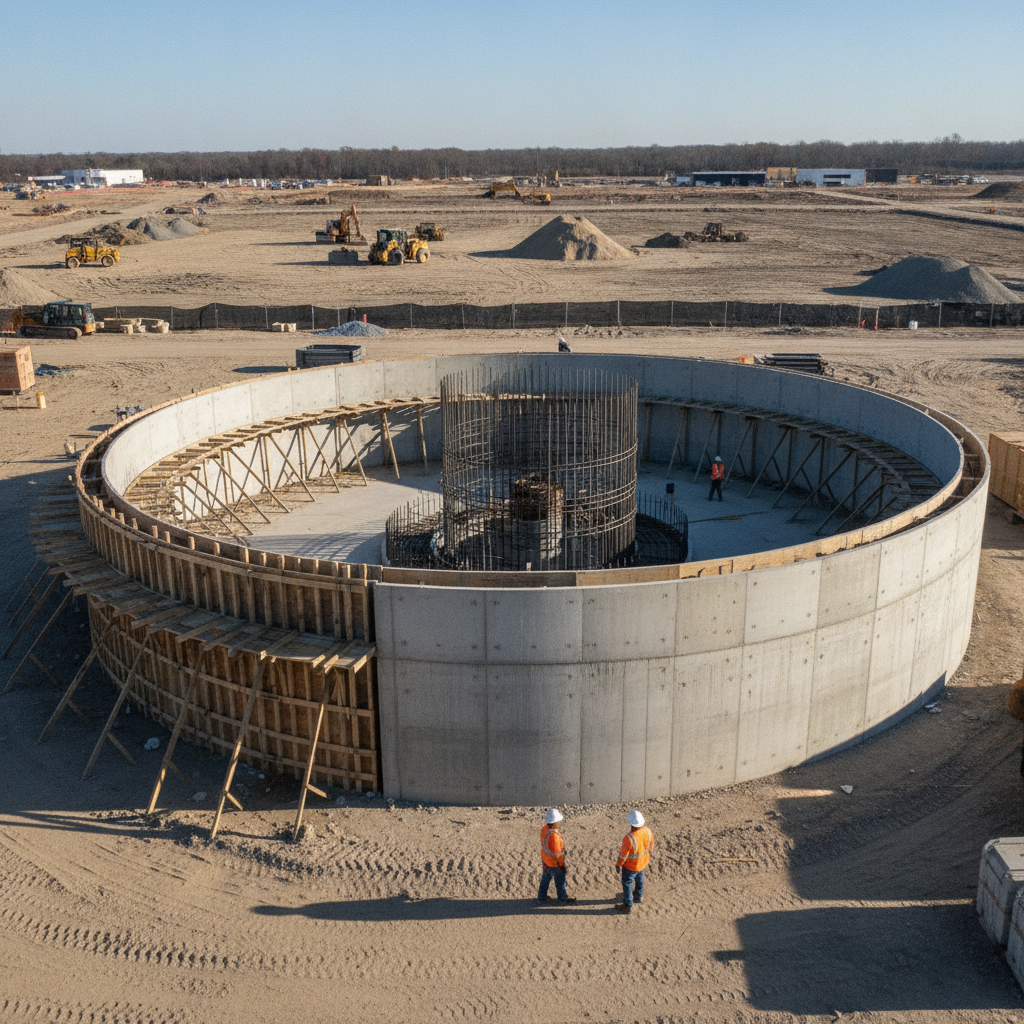
For most vertical, cylindrical ASTs on sites with competent soils, designers choose between two primary shallow foundation types: a ring wall or a full mat slab. A ring wall foundation is a reinforced concrete ring constructed directly beneath the tank’s shell. It is effective at transferring the concentrated load of the tank wall and its contents into the underlying soil. The interior of the ring is typically filled with a compacted, free-draining material like sand or crushed stone, which provides uniform support for the tank floor. This approach can be cost-effective but is best suited for stable, predictable soil conditions. A full reinforced concrete slab foundation, or mat slab, provides support across the entire footprint of the tank. This design distributes the load over a larger area, making it ideal for sites with lower bearing capacity soils or where minimizing differential settlement is critical. While often more expensive due to the increased volume of concrete and reinforcing steel, a mat slab offers superior rigidity and can be designed as an integral part of the secondary containment structure, creating a monolithic and robust system. The choice between these systems is a key decision driven by the Geotechnical soil report and project-specific requirements.
Addressing Buoyancy and Hydrostatic Forces
In areas with a high groundwater table, an empty or partially full fuel tank can behave like a boat, becoming buoyant and susceptible to uplift forces. This hydrostatic pressure can be powerful enough to lift the tank and its foundation, causing catastrophic damage to the tank and connected piping. The foundation design must therefore provide sufficient resistance to counteract this uplift potential. This is a critical life-safety and operational consideration in the overall site development plan. Strategies to resist buoyancy include increasing the dead weight of the foundation by making the slab thicker or wider, or employing deep foundation elements like piles or drilled shafts that can resist tension forces. Proper drainage design around the tank yard is also crucial for managing surface water and helping to control groundwater levels. It is essential to note that hydrogeological conditions and foundation design requirements vary by jurisdiction, and every project team should confirm the applicable standards with the local, state, regional, and federal authorities that hold review authority over the site. A comprehensive approach ensures the tank remains stable under all conditions.
Secondary Containment Design and Integration
Federal, state, and local regulations mandate secondary containment for bulk fuel storage to prevent spills from contaminating soil and water resources. The foundation design is intrinsically linked to the containment strategy. The most common approach for data centers is to construct a reinforced concrete containment basin, often using the tank’s foundation slab as the floor and adding concrete containment walls around the perimeter. The containment structure must be designed to be liquid-tight and have sufficient volume, typically 110% of the volume of the largest tank within the basin, plus additional volume for precipitation (known as freeboard). This requires careful attention to concrete mix design, reinforcement to control cracking, and the application of fuel-resistant coatings. The design must also incorporate a system for managing stormwater management, such as a sump and pump or a manually operated valve, to remove accumulated rainwater while ensuring no fuel is inadvertently discharged.
Anchorage for Seismic and Wind Loads
Aboveground storage tanks present a large surface area and can be subject to significant lateral forces from high winds and seismic events. The foundation plays a critical role in anchoring the tank to resist these forces and prevent overturning or sliding. The design of the anchorage system is governed by national standards and model codes, such as ASCE 7, which provides methodologies for calculating wind and seismic loads based on the project’s geographic location and site-specific conditions. The anchorage system typically consists of high-strength anchor bolts embedded in the concrete foundation, which are then connected to anchor chairs or clips welded to the tank shell. The structural engineer must calculate the overturning moments and shear forces to determine the required number, size, and embedment depth of the anchors. This is a highly collaborative effort requiring close coordination between the civil engineering team, the structural engineer, the geotechnical engineer, and the tank manufacturer to ensure a fully integrated and resilient design.
Coordination with Piping, Venting, and Access
A successful fuel tank installation is not just about the foundation; it’s about how the entire system works together. The civil engineering design must be closely coordinated with mechanical, electrical, and plumbing (MEP) engineers. The foundation design must account for penetrations for fuel supply and return piping, ensuring proper clearance and sleeving to prevent point loads on the concrete and allow for thermal expansion or minor settlement. Furthermore, the overall site plan design must provide adequate access for fuel delivery trucks, including appropriate turning radii and pavement sections designed for heavy vehicle loads. The location of the offloading station, emergency shutoffs, and vent pipes must be carefully planned to meet operational needs and safety codes. This level of detailed utility coordination ensures that all components of the fuel system are integrated seamlessly, from the foundation up.
How RSP Engineers Approaches Fuel Tank Foundation Design
At RSP Engineers, we recognize that a fuel tank foundation is a critical component of mission-critical infrastructure. Our approach is comprehensive and collaborative. We begin every project by commissioning or closely reviewing the Geotechnical soil report to build our design on a solid understanding of the site. Our team of Civil engineers works in lockstep with structural and MEP engineers, as well as the client and tank vendor, to develop an integrated design. Our process emphasizes a holistic view of the generator yard, ensuring the foundation, secondary containment, access roads, and drainage design all function as a cohesive system. We manage the design and permitting process, preparing detailed construction documents and navigating the review process with the authorities having jurisdiction. Our goal is to deliver a safe, compliant, and durable design that provides a literal foundation for our clients’ operational continuity.
Common Issues and Design Challenges
Even with careful planning, fuel tank foundation projects can encounter challenges. One of the most common issues is proceeding with a design based on insufficient or outdated geotechnical data, which can lead to costly change orders or long-term settlement problems. Another frequent challenge is a lack of coordination between disciplines, resulting in conflicts between foundation elements and underground piping or electrical conduits. Underestimating hydrostatic uplift forces in areas with fluctuating groundwater is a significant risk that can lead to foundation failure. On the materials side, improper concrete mix design or inadequate application of containment coatings can compromise the system’s integrity and lead to environmental compliance issues. Finally, overlooking the need for rigorous quality control and inspection during construction can allow small errors to become major problems, highlighting the importance of thorough Construction Management Services.
Partner with RSP Engineers for Your Mission-Critical Infrastructure
Ensuring the reliability of your data center’s backup power system starts from the ground up. A robust, intelligently designed fuel tank foundation is not a commodity; it’s a critical investment in operational resilience. The team at RSP Engineers has the expertise to guide your project through every phase, from initial site development and geotechnical coordination to detailed engineering and navigating the complexities of agency permitting. Don’t leave this critical system to chance. Contact us today to discuss how our civil engineering services can support your mission-critical facility.
Conclusion: A Foundation for Uninterrupted Operations
The foundation for an aboveground fuel storage tank is far more than a simple concrete pad. It is a highly engineered system that must safely support immense weight while resisting complex environmental forces. A successful design requires a deep understanding of Geotechnical Engineering, detailed structural analysis, and holistic civil engineering to integrate drainage, access, and containment. By investing in a thorough, well-coordinated design process, data center owners and operators can build a literal foundation for the uninterrupted operations that their clients demand.
FAQs
-
The most critical factor is a comprehensive geotechnical investigation. The subsurface soil and groundwater conditions dictate nearly every aspect of the design, from the foundation type and size to the need for buoyancy resistance and settlement mitigation. Without an accurate Geotechnical soil report, the design is based on assumptions that introduce significant risk.
-
While specific requirements can vary, a common standard is to provide a containment volume equal to 110% of the capacity of the largest single tank within the containment area. Additionally, designers must account for precipitation by adding ‘freeboard’—extra wall height to contain rainfall from a significant storm event without overflowing. The final required volume must be confirmed with the applicable environmental regulations. Does the foundation design change for horizontal vs.
-
Yes, the design is fundamentally different. Vertical cylindrical tanks are typically supported on a continuous ring wall or a full mat slab. Horizontal tanks are cradle-mounted and supported on two or more concrete saddles, which are in turn supported by individual spread footings or a continuous slab. The structural engineering calculations for load transfer and stability are unique to each configuration.