
Battery Equipment Support Design for Data Centers
A technical guide to the structural engineering requirements for data center battery equipment, covering floor loads, seismic bracing, spill containment, and fire separation. Learn how to design robus
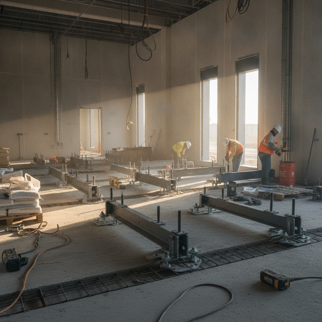
Understanding Extreme Floor Loading from Battery Systems
Battery systems, whether comprised of lead-acid, lithium-ion, or other chemistries, are characterized by extreme density. This results in highly concentrated loads that can far exceed the design capacity of typical commercial or industrial floor slabs. A standard data hall might be designed for 250-350 pounds per square foot (PSF), but a dedicated battery room often requires a floor loading capacity of 500 PSF, 1000 PSF, or even more, depending on the specific equipment layout and rack configuration. This demands a specialized structural slab design, often involving thickened reinforced concrete slabs, deep foundations, or structural steel framing to transfer loads safely to the underlying subgrade. The analysis must account for both static (dead) loads from the equipment’s weight and dynamic loads that occur during installation, maintenance, and seismic events. The project’s Professional Engineer must work closely with the BESS vendor to obtain precise equipment weights, footprints, and anchorage point locations. This data is critical for performing a detailed structural analysis to prevent slab deflection, cracking, or catastrophic failure. Neglecting these high-density loads is one of the most significant risks in a data center build-out or retrofit.
Seismic Bracing and Anchorage for Mission-Critical Uptime
Comparison of Support Strategies: Rack-Based vs. Containerized BESS
| Feature | Rack-Based BESS (Indoor) | Containerized BESS (Outdoor/Indoor) |
|---|---|---|
| Foundation Type | Thickened reinforced concrete slab-on-grade or elevated structural slab. | Dedicated concrete pad, strip footings, or pile foundation. Requires Geotechnical Engineering analysis. |
| Floor Loading Profile | Very high, concentrated point and line loads directly under rack posts. Requires robust slab design. | Loads are more distributed across the container's structural frame to the foundation. |
| Seismic/Wind Restraint | Requires extensive anchorage to the floor slab and potential overhead bracing to the building structure. | Anchored directly to the foundation pad. Must be designed for both seismic and regional wind loads. |
| Spill Containment | Integrated into the room design with curbs and chemical-resistant floor coatings. | Often built into the container, but may require a secondary external containment pad. |
| Installation Logistics | Requires careful rigging and movement of individual racks through the building. | Delivered as a single unit, requiring crane access and a prepared site for placement. |
| MEP Integration | Tightly integrated with building HVAC, fire suppression, and electrical systems. | Often a self-contained system, requiring only primary utility connections for power and cooling. |
In addition to vertical gravity loads, battery racks—especially tall, narrow ones—are highly susceptible to lateral forces from seismic events. Ensuring these systems remain operational after an earthquake is a primary objective of mission-critical design. The structural integrity of the BESS installation depends on a robust seismic bracing and anchorage design. This involves calculating the seismic forces based on the project’s location, site class, and the importance factor of the facility, often following standards like ASCE 7, Minimum Design Loads for Buildings and Other Structures. The design includes specifying heavy-duty post-installed or cast-in-place anchors to secure the rack base to the concrete slab, as well as designing bracing systems to prevent overturning forces. These systems can include overhead kickers, cross-aisle bracing, and connections to structural walls. Code requirements for seismic design and equipment anchorage vary by jurisdiction, and every project team should confirm the applicable standards with the local, state, regional, and federal authorities that hold review authority over the site. A failure in the anchorage system could lead to a complete loss of backup power, equipment damage, and life safety hazards.
Spill Containment and Chemical-Resistant Floor Systems
Many battery technologies carry the risk of electrolyte leakage, which can pose a hazard to personnel and damage the structural concrete slab. Therefore, battery rooms require specialized spill containment systems. This often involves constructing a monolithic, liquid-tight floor system with integrated concrete curbs around the perimeter of the battery area to contain a potential spill. The volume of this containment basin is typically dictated by code, often based on the volume of the largest single cell or unit. Furthermore, the concrete floor and curb surfaces must be protected with chemical-resistant coatings, such as multi-part epoxy or polyurethane systems. These coatings prevent corrosive electrolytes from degrading the concrete and reinforcing steel, preserving the structural integrity of the floor. The design must also coordinate with mechanical and plumbing engineers to incorporate appropriate drainage and neutralization systems, all while adhering to relevant safety standards, such as those from the National Fire Protection Association (NFPA).
Thermal Management and Fire Separation Strategy
Battery systems generate heat during operation and present a risk of thermal runaway, a dangerous condition that can lead to fire. The structural design must support the facility’s overall thermal management and fire protection strategy. This has direct implications for the layout and construction of battery rooms. For example, fire-rated construction, such as concrete masonry unit (CMU) walls or multi-layer gypsum board assemblies, is often required to isolate battery areas from the main data halls and other critical spaces. The structural engineer must perform MEP coordination with the mechanical and fire protection teams to accommodate large openings for ductwork, cooling pipes, and fire suppression systems without compromising the fire rating or structural capacity of the walls. Separation distances between battery racks and from racks to walls are also critical design parameters dictated by equipment vendor requirements and fire codes. The structural system must be designed to maintain its integrity under high-temperature conditions for a specified duration, ensuring the fire can be contained.
Critical Floor Flatness and Levelness Specifications
The proper installation and long-term performance of multi-rack battery systems depend on stringent floor flatness (FF) and floor levelness (FL) specifications. Battery racks are often bolted together in long rows, and an uneven floor can induce stress on the rack frames, busbar connections, and anchor points. This can lead to alignment issues, premature equipment failure, and difficulties during installation. Achieving high FF/FL numbers requires careful specification of the concrete mix design, placement techniques, and finishing processes. The structural drawings must clearly define the required tolerances, often referencing standards from the American Concrete Institute (ACI). Post-construction verification using specialized equipment is essential to ensure the specifications have been met before the battery vendor begins installation. Failure to achieve the required rack alignment can result in costly rework and project delays.
Designing for Battery Replacement and Maintenance Cycles
A data center’s lifespan is measured in decades, while battery systems typically need to be replaced every 5-15 years. The structural design must account for these future maintenance cycles from day one. This includes designing clear and structurally adequate equipment access paths from the loading dock to the battery room. These pathways must be able to support the weight of not only the new batteries but also the heavy equipment used to move them, such as forklifts or pallet jacks. This forward-looking life-cycle design may also involve incorporating embedded steel plates or rails for rigging, designing removable wall or floor panels for access, or ensuring the slab can handle the dynamic loading from lifting operations. Planning for replacement avoids costly and disruptive structural modifications years down the line, making it a crucial part of a sustainable and cost-effective data center design.
Our Process: Integrated Structural Design for BESS Facilities
At RSP Engineers, our approach to BESS support design is comprehensive and integrated. We begin with a thorough review of the owner’s project requirements and the battery vendor’s technical specifications. Our process involves close collaboration between our Civil engineers and structural teams, starting with a site-specific geotechnical investigation to inform foundation design. We then perform detailed structural analysis and modeling to design a floor and support system that safely manages the extreme loads. Our team excels at coordinating with architectural, mechanical, and electrical designers to ensure a seamless integration of structural components with fire protection, cooling, and power distribution systems. We produce a complete set of construction documents detailing all structural requirements, from concrete reinforcement to seismic anchorage specifications. Finally, we provide expert Construction Management Services and administration support to ensure the design is executed correctly in the field, verifying compliance and addressing any issues that arise during construction.
Common Challenges in Battery Support Design
Even with careful planning, several challenges can arise during the design and construction of BESS support structures. A primary issue is underestimating the true concentrated loads of the battery system, leading to an inadequate slab design that requires costly remediation. Another common pitfall is insufficient seismic bracing, which can be flagged during peer review or by the authority having jurisdiction, causing significant redesign and delays. Poor coordination between the structural engineer and MEP teams can result in conflicts between bracing, ductwork, and conduit, requiring field modifications that compromise the design intent. Furthermore, failing to specify and verify strict floor flatness tolerances can derail the battery installation schedule. Finally, a lack of planning for future battery replacement can create major operational headaches and expenses years after the facility is commissioned. Proactive and experienced engineering is the key to mitigating these common risks.
Partner with RSP Engineers for Your Mission-Critical Infrastructure
Designing robust support systems for data center battery equipment requires a specialized skill set that blends structural engineering, mission-critical facility knowledge, and a deep understanding of safety and code compliance. The team at RSP Engineers has the expertise to navigate these complex challenges. We provide comprehensive site engineering services, from initial Geotechnical Engineering and site planning to detailed structural engineering and construction administration. Whether you are building a new hyperscale campus or retrofitting an existing facility, we can deliver a design that ensures the safety, reliability, and longevity of your critical power infrastructure. Contact us today to discuss your project’s unique permitting and design requirements.
Conclusion
The structural support for a data center’s Battery Energy Storage System is a foundational element of its overall reliability. A successful design must holistically address extreme floor loads, seismic and wind forces, chemical spill containment, and thermal safety considerations. By focusing on a detailed and integrated approach that includes robust structural engineering, diligent MEP coordination, and planning for the full operational life cycle, developers can ensure their mission-critical facilities are built on a foundation of safety and resilience. Partnering with experienced Civil engineers is the first step toward achieving that goal.
FAQs
-
While it varies based on the specific battery technology and rack density, it is common to see design requirements ranging from 500 to over 1,000 pounds per square foot (PSF). This is significantly higher than standard data hall loading and requires a purpose-built structural slab design.
-
In areas with higher seismic risk, the design must account for significant lateral forces. This translates to more robust anchorage design, larger anchor bolts, thicker base plates, and potentially extensive overhead structural steel bracing to prevent the racks from overturning during an earthquake.
-
For most battery chemistries that use a liquid electrolyte (like certain lead-acid or flow batteries), a chemical-resistant coating is essential to protect the concrete structure from corrosive spills. It is a critical component of the overall safety and spill containment strategy.