
Data Center Underground Duct Bank Design Guide
A comprehensive guide for data center developers on underground duct bank design in Florida, covering conduit configuration, thermal derating, permitting, and utility coordination.
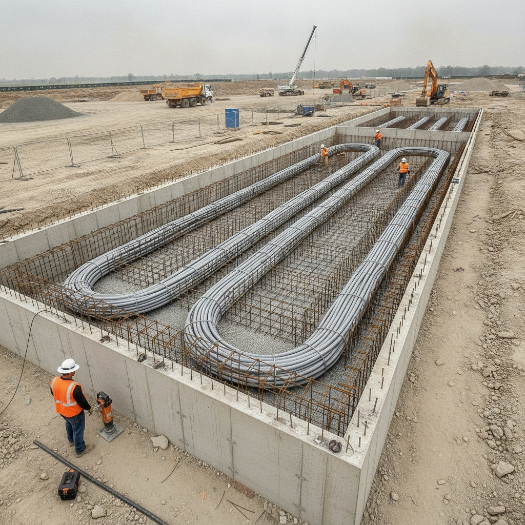
Conduit Configuration and Spacing: The Foundation of Reliability
The internal geometry of a duct bank is fundamental to its long-term performance and constructability. The conduit configuration—the arrangement of individual conduits in a grid (e.g., 4×5, 6×6)—is determined by the number of circuits required, voltage levels, and future expansion plans. However, simply packing conduits together is a recipe for failure. Proper spacing is critical for two primary reasons: thermal performance and structural integrity. A minimum separation, typically 3 inches, must be maintained between all conduits. This spacing allows for adequate flow of concrete during the pour, ensuring a void-free concrete encasement that provides uniform support and protection. More importantly, this separation is crucial for heat dissipation. Without it, heat from high-voltage cables can become trapped, leading to a significant reduction in conductor efficiency, a phenomenon known as ampacity derating. We use specialized spacers and chairs to lock conduits into their specified positions within the rebar cage before the concrete pour, guaranteeing the design geometry is maintained throughout construction.
Concrete Encasement and Structural Integrity
Duct Bank Design Parameters Comparison
| Parameter | Standard Duty (Landscaped Areas) | Heavy Duty (H-20 Roadway Loading) | Key Florida Consideration |
|---|---|---|---|
| Minimum Depth of Cover | 24 inches | 36 inches | Must be maintained after accounting for any grading, swales, or future excavation. |
| Concrete Encasement Strength | 3,000 PSI | 4,000 PSI | Mix design should account for potentially corrosive, high-sulfate soils. |
| Reinforcement | Single mat of rebar (top) | Full rebar cage (top & bottom) | Essential for bridging over pockets of loose sand or organic material to prevent settlement. |
| Conduit Material | PVC Schedule 40 | PVC Schedule 80 or HDPE | Schedule 80 provides superior structural resistance against compaction and traffic forces. |
| Backfill Material | Compacted native soil or sand | Compacted aggregate base or flowable fill | Backfill must be properly compacted in lifts to prevent surface settlement and protect the encasement. |
| Waterproofing | Standard manhole joints | Gasketed manholes with external waterproofing membrane | Critical for preventing water infiltration in areas with a high water table. |
The concrete that encases the conduit array serves as the primary defense against physical damage from excavation, settlement, and surface loads. The design of this concrete encasement is a core aspect of the civil engineering scope. Typically, a 3,000 to 4,000 PSI concrete mix is specified, often with a red dye additive to serve as a visual warning for any future excavation activities in the vicinity. A minimum of 3 inches of concrete cover is required around the entire conduit bundle. In Florida’s often-unpredictable soil conditions, reinforcing steel is not optional. A rebar cage is designed to provide the necessary structural integrity to resist bending and shear forces, preventing cracks or catastrophic failure due to soil settlement or heavy vehicle loads on the surface. The design must comply with the Florida Building Code and is heavily influenced by the findings of a site-specific Geotechnical soil report, which identifies soil bearing capacity and potential settlement risks. This structural hardening is a key component of building resilient infrastructure capable of withstanding Florida’s challenging environment.
Thermal Considerations and Ampacity Derating
Data centers consume immense amounts of power, and the cables carrying this load generate significant heat. If this heat is not effectively dissipated into the surrounding soil, the cable’s temperature will rise, increasing its electrical resistance and reducing its safe current-carrying capacity. This reduction is known as ampacity derating, and failing to account for it can lead to premature cable failure and facility downtime. The thermal analysis is a critical step in the design process, governed by the National Electrical Code (NEC) and sophisticated modeling. The analysis begins with understanding the thermal resistivity of the native soil, a value obtained from the Geotechnical Engineering investigation. In cases where native soils have poor thermal properties (like dry, sandy soils), we may specify a thermal backfill material. This can include a controlled low-strength material (CLSM) or a specialized thermal concrete with high thermal conductivity. Proper thermal management within the duct bank ensures that the power distribution system can operate at its full design capacity without risk of overheating.
Strategic Placement of Manholes and Pull Points
Underground duct banks are not continuous, monolithic structures. They require access points for installing, splicing, and maintaining cables. These access points come in the form of manholes or smaller pull boxes. The strategic placement of these structures is a critical utility coordination task that balances cable pulling limitations with overall site plan design constraints. Cable manufacturers specify a maximum pulling tension and a maximum number of bends (typically limited to 360 degrees of total bend between pull points). As a general rule, manholes are spaced every 400 to 600 feet on straight runs, with additional pull points required to accommodate sweeps and bends in the route. In Florida, manhole design must account for the high water table. This often requires specifying precast structures with watertight gaskets, external waterproofing membranes, and specialized pipe boots where conduits enter. The structural design of these manholes must also be sufficient to handle overlying traffic loads, making them a key element of the overall site engineering services.
Depth of Cover and Separation from Other Utilities
Determining the correct burial depth for a duct bank is a matter of code compliance and risk management. The depth of cover—the distance from the top of the duct bank to the final grade—is dictated by the National Electrical Code (NEC) and local utility provider standards. A typical minimum is 24 inches, but this increases significantly under roadways or other areas subject to heavy vehicle traffic (often 36 inches or more). The goal is to protect the infrastructure from accidental strikes during future construction or landscaping activities. Equally important is maintaining mandated horizontal and vertical separation from other utilities. A comprehensive utility coordination plan is essential to deconflict the duct bank route with existing and proposed water mains, sanitary sewers, gas lines, and especially stormwater management infrastructure like pipes and exfiltration trenches. A failure to properly map and separate these utilities during the design phase can lead to catastrophic conflicts during construction, causing significant delays and cost overruns. This is a primary focus during the permitting process with local agencies.
Duct Bank Routing and Site Constraints
The ideal duct bank route is a straight line, but on a complex data center campus, this is rarely possible. The duct bank routing process is an exercise in navigating numerous site constraints while adhering to engineering best practices. The route must avoid building foundations, column footings, sensitive environmental areas, and future expansion zones. It must be carefully coordinated with the site’s grading and drainage design to ensure proper cover is maintained and to avoid conflicts with swales, retention ponds, and underground stormwater systems. When a duct bank must cross an access road or public right-of-way, principles of roadway engineering come into play, often requiring deeper burial, thicker encasement, or even specialized construction methods like jack-and-bore. This entire process must be integrated with the overall site plan design and supported by precise survey data to ensure the final alignment is constructible and compliant with all zoning compliance requirements, such as utility easements and setbacks.
The RSP Engineers Approach to Duct Bank Design
At RSP Engineers, we treat duct bank design as an integrated component of the overall site development strategy. Our process is collaborative and proactive, designed to mitigate risk and ensure a smooth path from concept to construction. As one of the leading Civil Engineering Firms in Florida, we follow a proven methodology. First, we initiate early utility coordination with the power company and fiber providers to align on requirements and points of connection. Second, we manage a thorough Geotechnical Engineering investigation to understand the subsurface conditions that will dictate our design. Third, our Civil engineers integrate the duct bank routing with the comprehensive stormwater management plan, grading, and other site utilities to create a conflict-free design. Fourth, we prepare detailed permit submittals for all relevant agencies, ensuring a clear and defensible design that facilitates a timely agency review. Finally, we provide robust Construction Management Services to oversee installation, ensuring the final product is built to specification.
Common Issues and How to Avoid Them
Even with a solid design, issues can arise during construction. Proactive planning and quality control are key to avoiding them. One common problem is improper conduit spacing, which can lead to thermal hotspots or concrete voids. This is prevented with rigorous inspection before the pour. Another issue is insufficient soil compaction around the duct bank, which can cause settlement and structural failure over time; this is addressed through a strict compaction testing protocol. In Florida, water infiltration into manholes and conduits is a major concern. Specifying high-quality waterproofing systems and ensuring proper installation is critical. The most disruptive issue, however, is discovering unforeseen utility conflicts during excavation. This is best avoided through comprehensive utility locating services (SUE) and a meticulous utility coordination process during the design phase. A proactive approach to these potential pitfalls saves time, money, and protects the project’s integrity.
Your Partner for Mission-Critical Site Development
Designing and permitting mission-critical infrastructure in Florida requires specialized expertise and a deep understanding of local conditions. The success of a multi-million dollar data center can hinge on the integrity of its underground utilities. At RSP Engineers, our team of Florida Licensed Engineers provides the expert guidance needed to navigate these complexities. We specialize in comprehensive site development, from initial due diligence and zoning compliance to final construction administration. Don’t leave your critical infrastructure to chance. Contact RSP Engineers today to discuss how our site engineering services can support your data center project. We are your trusted partner for robust utility coordination, efficient permitting, and resilient design.
Conclusion: Building Resilient Infrastructure from the Ground Up
The design of an underground duct bank for a data center is far more than just trenching and laying pipe. It is a sophisticated civil engineering discipline that directly impacts the facility’s long-term reliability and operational success. By carefully considering conduit configuration, thermal performance, structural hardening, and seamless integration with the overall site development plan, we can create infrastructure that is both robust and resilient. For data center developers in Florida, a proactive and technically sound approach to underground utility design is the first and most critical step in building for the future.
FAQs
-
While all factors are important, accounting for Florida’s unique environmental conditions is paramount. This includes designing for a high water table with robust waterproofing, understanding the soil’s thermal and structural properties through a detailed Geotechnical soil report, and ensuring the entire system is hardened against potential storm-related impacts. Integrating the drainage design with the duct bank routing is also critical.
-
The local utility provider (e. g. , FPL, Duke Energy, TECO) has specific and non-negotiable standards for duct bank construction, manhole specifications, and conduit materials that will be under their ownership. Early and frequent utility coordination is essential to ensure the design complies with their requirements, which is a prerequisite for receiving service and passing inspections.
-
PVC Schedule 40 may be acceptable in areas with no vehicle traffic, but for conduits under roadways, parking lots, or in deep installations, PVC Schedule 80 is the standard due to its superior crush strength. High-Density Polyethylene (HDPE) is another excellent option, often used for directional boring applications. The choice depends on the specific application, geotechnical conditions, and utility provider requirements.