
Data Center Spread Footing Design
A technical guide for developers on data center spread footing design, covering sizing, shear checks, reinforcement, and subgrade preparation from a Florida civil engineering perspective.
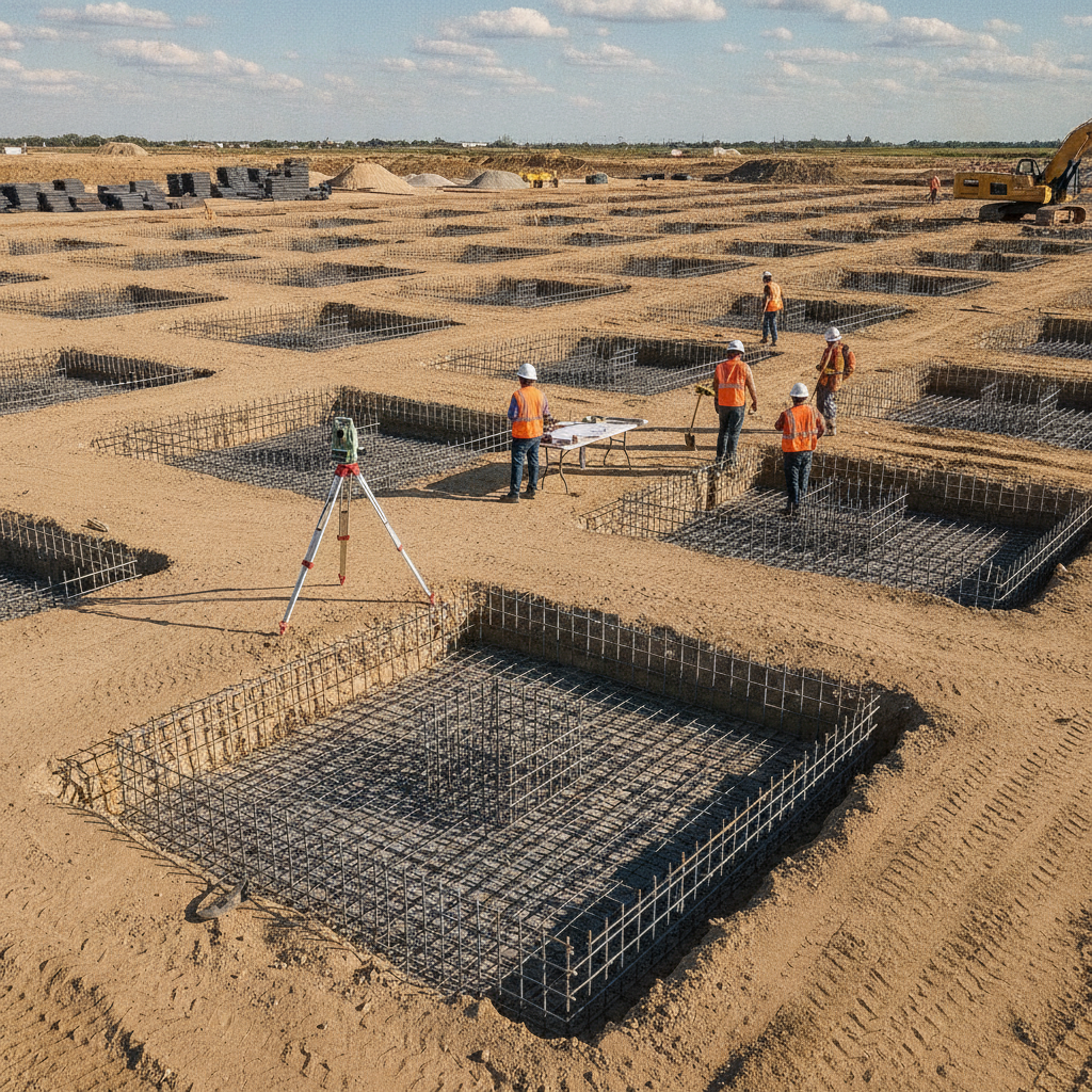
Geotechnical Investigation: The Foundation of Foundation Design
Before any structural calculations can begin, a comprehensive geotechnical investigation is non-negotiable. This process, led by a qualified Geotechnical engineer, provides the essential data upon which all foundation design decisions are based. For a data center, where even minor differential settlement can compromise sensitive equipment and structural integrity, this step is paramount. The investigation typically involves a series of Soil boring tests across the proposed building footprint to characterize the subsurface conditions. The primary output of this investigation is the Geotechnical soil report. This document establishes the allowable bearing pressure of the soil—the maximum pressure the soil can safely support. It also identifies the depth of the water table, the presence of problematic soil layers (like organic materials or loose sands common in Florida), and provides recommendations for subgrade preparation. Overlooking or under-scoping the Geotechnical Engineering phase introduces significant risk that can lead to costly change orders or long-term structural issues.
Sizing Spread Footings from Column Loads and Bearing Capacity
Data Center Foundation Design Parameters by Load Type
| Load Source / Equipment | Key Design Driver | Geotechnical Consideration | Civil/Site Coordination Requirement |
|---|---|---|---|
| Main Structural Columns (Steel Frame) | High axial load and potential frame moments. Governed by punching shear and bearing pressure. | Uniform bearing capacity across all column locations is critical to prevent differential settlement. | Precise layout and elevation control. Coordination with anchor bolt placement. |
| Exterior Precast/Tilt-Up Wall Panels | Continuous line load. Governed by one-way shear and flexure in the footing. | Requires consistent subgrade support along the entire building perimeter. | Coordination with building perimeter, finished floor elevation, and exterior grading. |
| Backup Generator Pads | Extreme dead weight plus significant dynamic/vibratory loads. Often requires an isolated inertia base. | Potential for soil liquefaction or settlement under vibration must be assessed. May require soil improvement. | Requires coordination with fuel lines, electrical conduits, and exhaust systems. Often involves separate permitting. |
| Exterior Cooling Units (Chillers/Pumps) | Concentrated static weight and operational vibrations. | Bearing surface must be protected from erosion or washout from stormwater or condensate. | Close coordination with mechanical piping, electrical feeds, and site drainage design. |
| Interior Equipment Slabs (CRAC/CRAH/UPS) | High floor loading (psf). Often designed as a thickened slab-on-grade integral with footings. | Subgrade must be uniformly compacted to prevent slab settlement under heavy, static loads. | Intensive utility coordination for power, cooling lines, and floor drains beneath the slab. |
The fundamental principle of spread footing design is to distribute concentrated column loads over a wide enough area to keep the pressure on the underlying soil below its allowable bearing pressure. The basic calculation is straightforward: Footing Area = Total Load / Allowable Bearing Pressure. However, the ‘Total Load’ is a complex combination of dead loads (the permanent weight of the structure), live loads (occupants, furniture, and non-permanent equipment), and transient loads from wind and seismic forces as defined by the Florida Building Code. A Professional Engineer must carefully calculate these load combinations to determine the governing case for each footing. For data centers, this includes the immense weight of electrical switchgear, UPS systems, battery racks, and cooling equipment. The design must be conservative, ensuring that the footing is sized for the worst-case loading scenario to prevent settlement. This phase requires close collaboration between the structural engineer and the civil engineering firm near me to ensure the site layout can accommodate the required footing dimensions.
Addressing Eccentricity: Combined and Strap Footing Solutions
Columns are not always located in the center of their footings. When a column is situated near a property line or another obstruction, it creates eccentric loading, where the load’s line of action does not pass through the footing’s geometric center. This induces a bending moment in the footing, causing uneven pressure distribution on the soil beneath it. If not properly addressed, this can lead to tilting and excessive differential settlement. Two common solutions are employed to counteract eccentricity. A combined footing is a single, often rectangular or trapezoidal, footing that supports two or more columns, balancing the loads from an exterior and interior column. A strap footing (or cantilever footing) connects an eccentrically loaded footing to an interior, concentrically loaded footing with a grade beam. This strap beam acts as a lever, transferring the moment away from the eccentric footing and preventing rotation. The selection of the appropriate solution is a key aspect of the detailed site plan design.
Shear Analysis: Punching Shear and One-Way Shear Checks
While ensuring adequate bearing area is crucial, the footing’s thickness is often governed by its ability to resist shear forces. There are two primary modes of shear failure in a spread footing. Punching shear (or two-way shear) is the tendency of a concentrated column load to ‘punch’ through the footing slab. This is checked on a critical perimeter at a specified distance from the column face. The concrete’s shear strength and the footing’s effective depth are the primary factors in resisting this force. The second mode is one-way shear (or beam shear), which acts across the entire width of the footing at a critical section away from the column face, similar to how a beam would fail in shear. Both shear conditions must be checked against the capacity limits defined in structural codes like ACI 318. If shear stresses are too high, the most common solution is to increase the footing thickness, as adding shear reinforcement in footings is often impractical and costly. This analysis is a critical part of the site engineering services provided by the design team.
Reinforcement Design and Minimum Embedment Requirements
Once the footing dimensions are finalized and shear is checked, the steel reinforcement (rebar) is designed to resist the flexural (bending) stresses. The upward pressure from the soil creates tension at the bottom of the footing, requiring a mat of rebar in both directions. The design involves calculating the required area of steel based on the bending moment and ensuring compliance with minimum reinforcement ratios to control temperature and shrinkage cracking. Proper concrete cover over the rebar is also critical, especially in Florida’s corrosive environment, to ensure long-term durability. Additionally, footings must have a minimum embedment depth. While frost protection is the primary driver in colder climates, in Florida, embedment is necessary to get below any topsoil or unsuitable surficial soils and reach the competent bearing stratum identified in the Geotechnical soil report. This also provides lateral stability and protects the bearing soils from erosion or disturbance. This depth requirement directly impacts the overall site development excavation plan.
Subgrade Preparation, Acceptance, and Proofrolling
A perfectly designed footing will fail if placed on an improperly prepared subgrade. The site development process begins with excavating to the planned footing elevation. The bearing surface must be firm, uniform, and free of loose material or standing water. Before any concrete is placed, the subgrade must be verified by the Geotechnical engineer or a designated inspector to confirm it meets the project specifications and matches the conditions assumed in the design. A critical step in this verification process is proofrolling. This involves driving a heavy, loaded vehicle (like a dump truck or scraper) over the entire building pad and footing areas. The purpose is to identify any soft, weak, or unstable zones that deflect under the load. These areas must be over-excavated and replaced with compacted, engineered fill. Proper subgrade preparation and verification are essential to prevent post-construction settlement issues that could jeopardize the data center’s operations.
Coordinating Footings with Underslab Utilities and Drainage
One of the most complex aspects of data center foundation work is the intense level of utility coordination required. An extensive network of electrical conduits, grounding grids, and plumbing must be routed beneath the slab and through the foundation system. This coordination must happen during the design phase, not in the field. Penetrations through footings must be carefully located and detailed to avoid compromising structural integrity. Sleeves are often cast into the concrete to allow for future utility runs without core drilling. Effective drainage design is also integrated at the foundation level. Footing drains may be required to intercept groundwater and prevent hydrostatic pressure on the slab, particularly in areas with a high water table. A properly designed underslab drainage system, often consisting of a layer of clean stone and perforated pipes, is crucial for controlling moisture. This integration of utilities and drainage is a hallmark of high-quality civil engineering for mission-critical projects.
Our Process: Integrated Foundation Design and Site Development
At RSP Engineers, we approach data center foundation design as an integrated, multi-disciplinary process. Our methodology ensures that all critical factors are considered from the outset, minimizing risks and streamlining the path to construction. Collaborative Geotechnical Review: We work directly with the Geotechnical engineer to interpret the soil report, not just accept it. We ask critical questions to understand the risks and opportunities presented by the site’s subsurface conditions, ensuring the foundation strategy is both safe and cost-effective. Integrated Structural & Civil Modeling: Our structural and civil teams use shared models to overlay foundation plans with utility networks, grading, and drainage systems. This proactive utility coordination prevents costly conflicts in the field and ensures a seamless design. Rigorous Agency Permitting & Review: We manage the entire permitting process, preparing comprehensive submittal packages that clearly demonstrate compliance with the Florida Building Code and local ordinances. Our experience with Florida agencies helps anticipate comments and expedite approvals. Construction Administration & Field Verification: Our involvement doesn’t end with the design. We provide robust Construction Management Services, including subgrade inspections, rebar placement verification, and concrete testing coordination, to ensure the foundation is built exactly as designed.
Common Pitfalls in Data Center Foundation Design
Even with a solid plan, several common issues can arise during the design and construction of data center foundations. A primary pitfall is relying on an inadequate or outdated Geotechnical soil report, which can lead to a fundamentally flawed design. Another frequent problem is poor coordination of underslab utilities, resulting in last-minute, unapproved field modifications that can compromise the foundation’s integrity. Finally, insufficient field oversight during subgrade preparation and proofrolling can allow hidden soft spots to go undetected, leading to long-term settlement problems that are extremely difficult and expensive to remediate.
Partner with RSP Engineers for Your Mission-Critical Facility
The success of your data center hinges on a foundation designed with precision, foresight, and a deep understanding of Florida’s unique engineering challenges. At RSP Engineers, we provide the integrated expertise required for these complex projects. Our team of Florida Licensed Engineers excels at navigating the entire project lifecycle, from initial due diligence and site development planning to complex utility coordination and securing agency permitting. We deliver robust, reliable, and cost-effective foundation and site designs that provide the stability your mission-critical infrastructure demands. Contact us to discuss how our site engineering services can support your next data center development.
Building Resilient Data Centers from the Ground Up
In conclusion, the design of spread footings for data centers is a sophisticated process that extends far beyond simple sizing calculations. It requires a holistic approach that integrates structural mechanics, geotechnical engineering, and practical civil engineering. By prioritizing a thorough site investigation, meticulous load analysis, and seamless coordination between design disciplines and construction teams, developers can ensure their facilities are built on a foundation of stability and long-term reliability. Ultimately, a well-designed foundation is the first and most critical step in safeguarding a multi-million dollar investment in digital infrastructure, ensuring operational continuity through robust construction administration and design.
FAQs
-
Florida’s geology, with its sandy soils and high water table, presents unique challenges. The design must account for lower allowable bearing pressure in loose sands. A dewatering plan is often required during construction to keep excavations dry. The foundation design must also consider potential hydrostatic uplift pressures on the slab and the increased need for robust corrosion protection for reinforcement. What is the role of the civil engineer vs.
-
It’s a collaborative effort. The structural engineer is primarily responsible for sizing the footing, calculating shear and moment, and designing the steel reinforcement based on building loads. The Civil Engineer near me is responsible for the context in which the footing exists: the overall site development, grading, drainage design, subgrade preparation specifications, and the critical utility coordination around and under the foundation.
-
Data centers have zero tolerance for differential settlement. Proofrolling is the most effective field method to verify that the entire building pad provides uniform support. It’s a final quality control check that ensures the assumptions made by the Geotechnical engineer and structural designer hold true across the entire site, preventing future slab cracks or equipment misalignment.