
Data Center Heavy Equipment Pad Design
A technical guide to designing heavy equipment pads for data centers. Learn about load calculations, subgrade prep, reinforcement, and utility coordination from Florida’s civil engineering experts.
The Critical Role of Geotechnical Investigation
Before any concrete is poured, the design process must begin below the surface. A comprehensive Geotechnical Engineering investigation is the non-negotiable first step in designing a reliable equipment pad. This process involves conducting a Soil boring test to determine the subsurface soil profile, locate the water table, and collect samples for laboratory analysis. The resulting Geotechnical soil report provides the essential data our engineers need to design the foundation system. This report quantifies the soil’s safe bearing capacity—the maximum pressure the ground can withstand without failure or excessive settlement. It also identifies potential issues like loose sands, organic materials, or a high water table, which are common in Florida’s geology. Ignoring this step or relying on assumptions is a significant risk. An inadequate foundation design based on poor geotechnical data can lead to differential settlement, where one part of the pad sinks more than another, causing equipment misalignment, structural stress, and potential failure.
Analyzing Static and Dynamic Load Conditions
Equipment-Specific Pad Design Considerations
| Equipment Type | Primary Load Type | Key Design Consideration | Common Reinforcement Detail |
|---|---|---|---|
| Outdoor Transformer | Static, Concentrated | Oil containment (secondary containment curb or vault), grounding grid integration, and significant point loads at support points. | Thickened slab with heavy top and bottom rebar mats; integrated containment curb reinforcement. |
| Chiller Unit | Static & Dynamic | Vibration isolation, precise anchor bolt layout for multiple support feet, and accommodation for large-diameter piping. | Thickened pad, often designed as an inertia base with pockets for spring isolators. |
| Backup Generator | Heavy Dynamic & Static | Vibration and acoustic control, fuel line and exhaust routing, and foundation mass sufficient to dampen engine vibration. | Massive concrete inertia base on spring or pad isolators, often structurally separate from the main building slab. |
| Main Switchgear | Static, Distributed | Precise alignment, extensive underslab conduit routing, and levelness for cabinet installation. | Uniform thickness slab with top rebar mat, thickened edges, and meticulous conduit layout. |
| UPS & Battery Racks | Static, High Density | High floor loading (psf), acid-resistant coatings, and thermal management considerations. | Heavily reinforced structural slab, often with a depressed area and specialized floor coatings. |
Data center equipment imposes two distinct types of loads on a foundation: static and dynamic. Static loads are the constant, dead weight of the equipment, such as a multi-ton transformer or switchgear cabinet. These are relatively straightforward to calculate. However, dynamic loads, generated by rotating or reciprocating machinery like chillers and backup generators, are far more complex. These loads introduce vibrations and cyclical forces that can cause fatigue in the concrete and instability in the underlying soil over time. Our engineering analysis involves quantifying both load types and modeling their effects on the pad and surrounding soil. For dynamic equipment, a vibration analysis is often necessary to ensure that the operational frequencies of the machinery do not match the natural frequency of the foundation system, a condition known as resonance that can lead to amplified vibrations and catastrophic failure. The design must account for the combined effects of these loads to prevent both immediate structural issues and long-term performance degradation.
Structural Design of Reinforced Concrete Pads
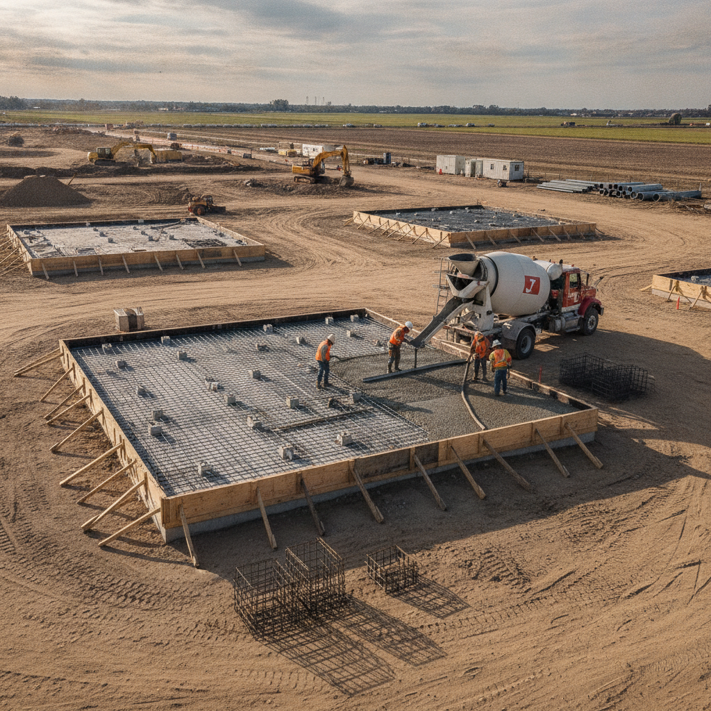
The structural design translates the load analysis and geotechnical data into a buildable plan. This involves determining the pad’s thickness, dimensions, and the specific requirements for steel reinforcement. For heavy, concentrated loads, a simple slab is often insufficient. We typically design pads with thickened edges or integrated grade beams to distribute loads more effectively and increase stiffness. For extremely heavy equipment, a mat foundation or even deep foundations like piles may be required. The design specifies the size, spacing, and grade of the rebar (reinforcing steel) needed to handle the tensile forces within the concrete. This reinforced concrete design is governed by codes from the American Concrete Institute (ACI) and the Florida Building Code. The design also includes details for control joints to manage shrinkage and thermal cracking, ensuring the pad’s long-term durability and structural integrity under constant operational stress.
Subgrade Preparation and Compaction Requirements
A concrete pad is only as stable as the ground it sits on. Subgrade preparation is a critical phase of the site development process that ensures the soil beneath the pad can uniformly support the design loads. The process often begins with stripping topsoil and undercutting any unsuitable materials like organic clays or debris identified in the geotechnical report. The area is then backfilled with a suitable, engineered fill material, such as crushed stone or clean sand, placed in controlled lifts. Each lift of fill must be compacted to a specific density, typically 95% to 98% of the maximum dry density as determined by a Modified Proctor test. This high level of compaction minimizes future settlement and provides a stable, unyielding platform for the concrete. Field density tests are performed throughout the process to verify that the compaction requirements are met. Insufficient compaction is a leading cause of foundation failure, leading to settlement, cracking, and costly remediation.
Integrating Underslab Utilities and Anchorage Systems
Modern data center equipment requires extensive connectivity. This means that equipment pads must be designed to accommodate a complex network of underslab utilities. Effective utility coordination is paramount. This involves precisely locating and sleeving for electrical conduits, grounding grids, communication cables, and drainage piping before the concrete pour. A failure to coordinate can result in costly and destructive core drilling or saw-cutting of the finished pad, which can compromise its structural integrity. Equally important is the design of the anchorage system. Equipment must be securely fastened to the pad to resist operational vibrations, wind loads, and, in some regions, seismic forces. This is achieved using cast-in-place anchor bolts or post-installed epoxy anchors. The design specifies the exact layout, size, and embedment depth of these anchors based on the equipment manufacturer’s requirements and structural calculations. A precise anchor bolt pattern is critical for a successful equipment installation.
Vibration Isolation for Sensitive and Dynamic Equipment
For equipment that generates significant vibrations, such as large diesel generators or rotary chillers, simply anchoring them to a rigid pad is not enough. Unchecked vibrations can travel through the ground and structure, potentially impacting sensitive IT equipment elsewhere in the data center. To mitigate this, specialized vibration isolation systems are incorporated into the foundation design. This is a key consideration in any mission-critical facility design. These systems can range from simple elastomeric pads placed between the equipment and the concrete to more complex spring isolators or engineered inertia bases. An inertia base is a secondary, massive concrete block that the equipment is mounted on, which is then isolated from the main equipment pad by springs or pads. This design uses the mass of the inertia block to dampen vibrations at their source, preventing their transmission and protecting both the equipment and the facility. This level of detail is a hallmark of high-quality site engineering services.
RSP’s Integrated Design and Permitting Process
At RSP Engineers, our approach to heavy equipment pad design is integrated and proactive. We begin by managing the Geotechnical Engineering investigation to ensure we have reliable data from day one. Our Civil Engineers then work in close collaboration with structural engineers, equipment vendors, and other trades to develop a holistic design. This integrated approach ensures that all requirements—from load-bearing capacity and utility coordination to vibration control and anchorage—are addressed in a cohesive plan. We translate this design into a comprehensive set of construction documents suitable for permit submittals to Florida agencies. Our experience with local jurisdictions helps streamline the agency review process, ensuring compliance with all relevant codes and regulations. During construction, we provide Construction Management Services and administration, performing site inspections to verify that subgrade preparation, reinforcement placement, and concrete work are executed exactly as specified in the design. This oversight is crucial for delivering a foundation that meets the stringent demands of a mission-critical facility.
Common Issues and Design Oversights
Even with a seemingly straightforward scope, several common issues can compromise the integrity of a heavy equipment pad. One of the most frequent is inadequate subgrade preparation, where contractors fail to achieve the specified compaction, leading to long-term settlement. Another is incorrect placement of the anchor bolt pattern, which can cause significant delays and costly rework during equipment installation. Miscommunication between civil, structural, and MEP (Mechanical, Electrical, Plumbing) engineers often leads to clashes with underslab utilities, requiring last-minute, and often compromising, design changes. Finally, underestimating dynamic loads is a critical oversight. A pad designed only for the static weight of a generator may experience cracking and instability once the machine is operational. A thorough design process anticipates these challenges, incorporating rigorous quality control checks and clear communication protocols to prevent these costly mistakes and ensure the final product aligns with the project’s mission-critical objectives.
Partner with RSP for Your Mission-Critical Project
Designing foundations for mission-critical infrastructure demands precision, experience, and a comprehensive understanding of how civil, structural, and MEP systems interact. At RSP Engineers, we provide the expert site engineering services needed to get it right. Our team excels at complex utility coordination, navigating Florida’s challenging soil conditions, and managing the permitting process for large-scale data center and industrial projects. We ensure your facility’s foundation is engineered for maximum reliability and long-term performance.
Conclusion
A data center’s heavy equipment pad is far more than a simple concrete slab; it is a critical engineered system that underpins the facility’s operational reliability. Proper design requires a multi-disciplinary approach, beginning with a thorough geotechnical investigation and extending through detailed structural analysis, meticulous utility coordination, and rigorous construction oversight. By focusing on key elements like load analysis, subgrade preparation, and vibration control, developers can ensure their infrastructure is built on a foundation of stability and resilience. Investing in expert civil engineering at this stage is essential for protecting valuable assets and ensuring uninterrupted service.
FAQs
-
There is no single answer. The thickness is a calculated value based on the specific equipment loads (both static and dynamic), the soil’s safe bearing capacity from the geotechnical report, and the reinforcement design. It can range from 8-12 inches for lighter switchgear to several feet for massive generators or chillers.
-
The Geotechnical Engineering investigation is arguably the most critical step. All subsequent structural calculations and design decisions are based on the data in the Geotechnical soil report. An inaccurate or incomplete report will lead to a flawed design, regardless of how well the rest of the engineering is performed.
-
Coordination is achieved through detailed planning and communication, typically using shared CAD or BIM models. We work with electrical and mechanical engineers early in the design phase to map out all underslab utilities. These locations are then incorporated into the structural drawings, showing exact locations for sleeves and block-outs to avoid conflicts with rebar and structural elements.