
Data Center Equipment Foundation Design
A technical guide to data center equipment foundation design in Florida. Learn about geotechnical analysis, load types, settlement control, and permitting from RSP’s civil engineers.
The Geotechnical Investigation: The Bedrock of Foundation Design
Before any concrete is poured, the foundation design process begins with a comprehensive geotechnical investigation. This is the most critical step, as it provides the empirical data needed to engineer a stable and predictable foundation system. A qualified Geotechnical engineer will perform a series of soil boring test procedures across the site to characterize the subsurface conditions. This investigation determines the soil’s composition, density, strength, and, crucially, its soil bearing capacity—the ability of the soil to support the immense loads from the equipment. The resulting geotechnical soil report is the foundational document for the structural engineer. It provides recommendations for the appropriate foundation type, anticipated settlement, and any necessary soil improvements. In Florida, this report is especially vital due to common challenges like loose sandy soils, organic layers, and a high water table, all of which can significantly impact foundation performance. Ignoring or under-scoping the geotechnical work is a direct path to long-term problems, including excessive or differential settlement that can compromise the entire facility’s structural integrity and operational stability.
Matching Foundation Type to Equipment Load and Sensitivity
Data Center Equipment Foundation Selection Matrix
| Foundation Type | Typical Equipment | Key Design Considerations | Relative Cost |
|---|---|---|---|
| Isolated Spread Footing | Static Switchgear, Transformers, Small Pump Skids | Sized for individual equipment load and soil bearing capacity. Simple to form and pour. | Low |
| Combined Footing | Paired Equipment, Columns near Equipment | Used when footings would otherwise overlap. Manages differential settlement between connected points. | Moderate |
| Mat / Raft Foundation | Large Generator Yards, Chiller Plants, Battery Rooms | Distributes heavy loads over a large area. Excellent for poor soils and controlling differential settlement. | High |
| Inertia Block | Large Reciprocating Engines, Generators, Chillers | A massive, thick foundation designed to resist dynamic loads and vibration through sheer mass. | High |
| Pile-Supported Foundation | Any Heavy Equipment on Very Poor/Compressible Soils | Transfers loads through weak upper soils to a competent bearing stratum deep underground. | Very High |
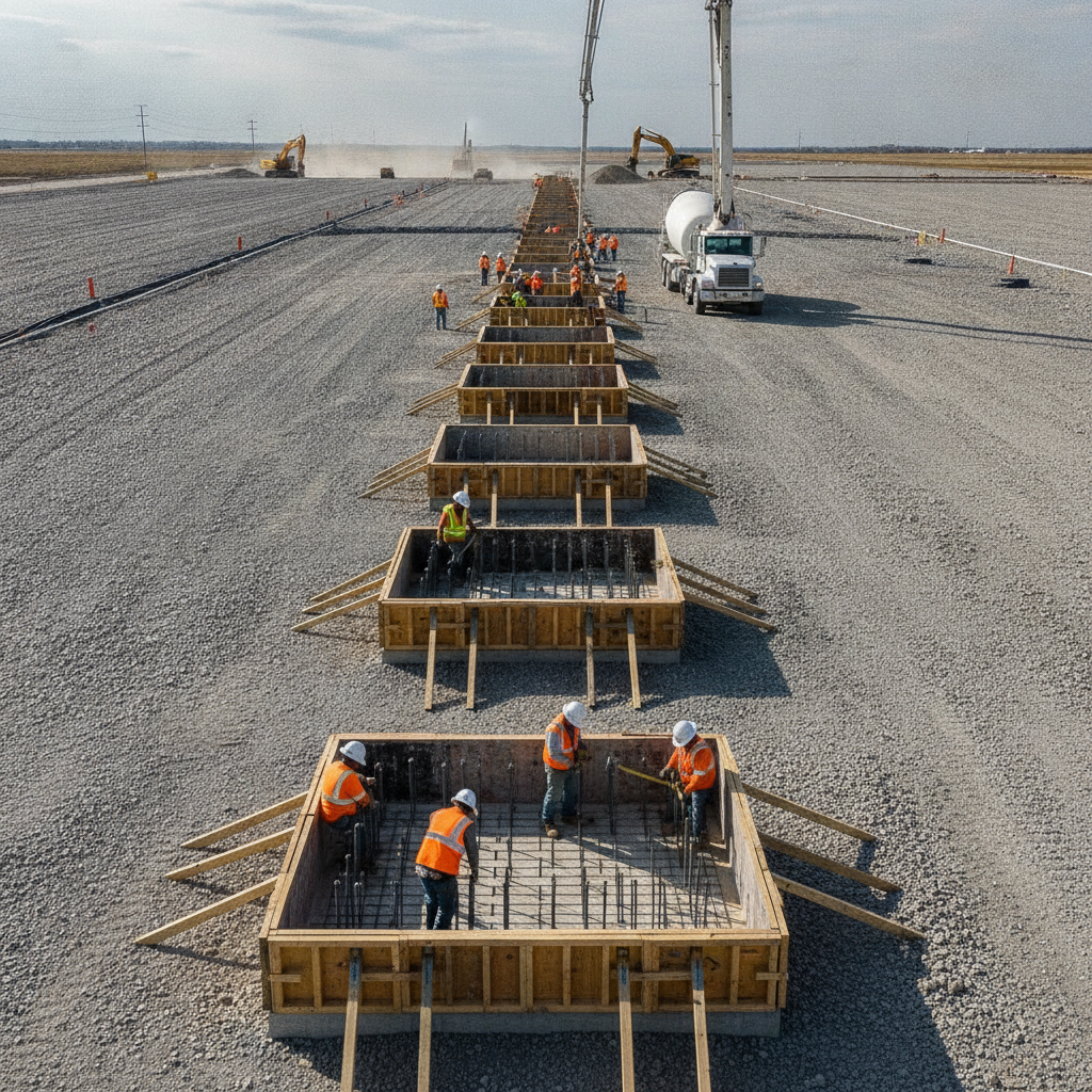
Data center equipment imposes a wide range of loads. A massive diesel generator has a completely different load profile—both static (dead weight) and dynamic (vibrational)—than a row of static switchgear cabinets. The civil engineering design must select the right foundation type for each specific application. The goal is to provide uniform support and manage settlement within the extremely tight tolerances required by equipment manufacturers. Common foundation types include isolated spread footings for individual pieces of equipment, combined footings that support multiple columns or a piece of equipment and an adjacent structural element, and large mat or raft foundations that support entire equipment yards. The choice depends on the equipment’s weight, footprint, sensitivity to movement, and the underlying soil conditions identified in the geotechnical report. For example, a heavy, vibration-producing generator may require a thick, heavily reinforced inertia block, which is a type of isolated mat foundation, to provide the mass needed to dampen vibrations and distribute the load safely. This careful selection is a core part of the overall site plan design.
Analyzing Dynamic Loads and Vibration Control
Many pieces of data center equipment, such as generators, chillers, and large pump skids, produce significant vibrations during operation. If not properly managed, these dynamic loads can cause structural fatigue, damage sensitive electronics, and even lead to foundation failure. The foundation design must account for the frequency and amplitude of these vibrations to prevent a condition known as resonance, where the equipment’s operating frequency matches the foundation’s natural frequency, leading to amplified and destructive motion. A key engineering task is to design a foundation with sufficient mass and stiffness to alter the system’s natural frequency, moving it far away from the equipment’s operating frequency. This is often achieved with a large concrete inertia base. In addition, specialized vibration isolators, such as neoprene pads or spring systems, are often installed between the equipment and the foundation to further dampen the transmission of vibrations. Proper vibration analysis and control are not just best practices; they are often required to maintain equipment warranties and ensure the long-term reliability of the facility. This is a critical component of professional site engineering services.
Anchorage, Grouting, and Load Transfer Mechanisms
A foundation is only effective if the load from the equipment is properly transferred to it. This is accomplished through a carefully designed system of anchor bolts and grout. Anchor bolts, specified by the structural engineer, must be sized and embedded deep enough into the concrete to resist all applicable forces, including operational vibrations, and in Florida, significant hurricane-force wind loads as mandated by the Florida Building Code. The placement of these bolts must be precise to match the equipment base plate, requiring close coordination during construction. After the equipment is set over the anchor bolts, the space between the steel base plate and the concrete foundation is filled with a high-strength, non-shrink grout. This grout creates a solid, monolithic connection, ensuring that loads are distributed evenly across the foundation surface without creating stress concentrations. Improper grouting is a common source of failure, leading to vibration issues and eventual anchor bolt fatigue. A diligent Professional Engineer will specify the exact grout material and installation procedure as part of the construction documents submitted for permitting.
Integrating Foundations with Site Drainage and Utility Infrastructure
Equipment foundations do not exist in a vacuum. They are an integral part of a complex site, interwoven with critical infrastructure. One of the most important integrations is with the site’s stormwater management system. The overall drainage design must ensure that water is directed away from equipment pads. Ponding water can saturate the subgrade soils beneath a foundation, reducing their bearing capacity and leading to settlement. This requires careful grading around the pads and strategic placement of storm drains. Furthermore, extensive utility coordination is required. Electrical conduits, fuel lines for generators, and chilled water piping must be routed to and from the equipment. These utilities often need to penetrate the foundation or be sleeved underneath it. This requires careful planning during the design phase to avoid conflicts and ensure that utility penetrations do not compromise the foundation’s structural integrity. This coordination is a hallmark of a well-executed civil engineering project and is essential for a smooth construction process.
Controlling Differential Settlement Across a Data Center Campus
While some minor, uniform settlement of a foundation is expected, differential settlement—where one part of a foundation or structure settles more than another—is a major concern for data centers. It can strain and break interconnected piping and electrical conduits, cause equipment to go out of alignment, and induce stress in the main building structure. For a data center campus with multiple buildings and outdoor equipment yards, ensuring consistent performance across all foundations is paramount. Controlling differential settlement starts with a thorough geotechnical investigation and uniform site preparation. All foundation areas must be prepared to the same standard of compaction and material quality. The structural engineer must then design all foundations—for both the building and the exterior equipment—based on the same set of geotechnical parameters and settlement criteria. This holistic approach, managed by experienced Civil Engineers, ensures that the entire campus settles uniformly, protecting the critical infrastructure that connects the various components of the facility. This is a key point of review during the agency review process for the site development permit.
The RSP Engineers Design and Permitting Process
At RSP Engineers, our approach to data center foundation design is systematic and thorough, ensuring all technical and regulatory requirements are met. Our process is designed to de-risk the project for our clients and deliver a robust, constructible design. Phase 1: Geotechnical Review and Site Assessment: We begin by commissioning or closely reviewing the geotechnical soil report, identifying all potential site constraints and opportunities. This includes analyzing soil bearing capacity, settlement potential, and groundwater levels. Phase 2: Load Analysis and Preliminary Design: We work with the client and equipment vendors to establish precise static and dynamic load data. We then develop a preliminary foundation layout, integrating it with the overall site plan design and performing initial sizing calculations. Phase 3: Detailed Engineering and Utility Coordination: Our structural and civil teams collaborate to produce detailed construction drawings. This includes reinforcement plans, anchor bolt layouts, grouting specifications, and seamless integration with the site’s drainage design and underground utility network. Phase 4: Permitting and Agency Review: We package the final design documents into a comprehensive set for permit submittals. We manage the application process and respond to comments from local Florida jurisdictions to secure timely approvals. Phase 5: Construction Administration Services: We remain engaged during construction, reviewing submittals, responding to contractor inquiries (RFIs), and performing site visits to verify that the foundations are being built in accordance with the design intent and specifications.
Common Issues and Design Oversights
Even with careful planning, several common issues can arise in equipment foundation projects. Proactive design and experienced oversight can prevent these costly mistakes: Inadequate Geotechnical Data: Basing a design on an incomplete or outdated geotechnical report is a primary cause of foundation settlement and failure. Ignoring Dynamic Loads: Designing a generator foundation based only on its static weight without proper vibration analysis can lead to excessive movement and equipment damage. Poor Utility Coordination: Discovering a conflict between a large-diameter pipe and a foundation footing in the field can cause significant delays and require expensive redesigns. Incorrect Anchor Bolt Placement: Misaligned anchor bolts are a common construction error that requires costly and time-consuming remediation, such as re-drilling and epoxying new anchors. Neglecting Site Drainage: Allowing water to pool around foundations can compromise the long-term stability of the subgrade, leading to settlement years after construction is complete. Frequently Asked Questions (FAQ) How does Florida’s high water table affect foundation design? A high water table can reduce the effective bearing capacity of sandy soils and may require dewatering during construction. For the long-term, it necessitates careful selection of foundation depth and may require corrosion-resistant coatings or specific concrete mix designs to protect the reinforcement from moisture. Proper stormwater management is also critical to prevent saturating the foundation subgrade. What is the difference between a geotechnical report and a structural design? The geotechnical soil report describes the existing ground conditions and provides recommendations, such as the allowable soil bearing pressure and estimated settlement. The structural design, performed by a Professional Engineer, uses that information to design the actual concrete and steel foundation—its thickness, dimensions, and reinforcement—to safely support the equipment loads. Can we place new, heavier equipment on an existing concrete slab? This requires a detailed structural analysis. An engineer must verify the existing slab’s thickness, reinforcement, and the soil conditions beneath it. In most cases, an existing slab-on-grade is not designed for heavy equipment loads, and a new, purpose-built foundation will need to be saw-cut into the slab and poured. How are future equipment upgrades considered in the initial design? A forward-thinking site plan design can accommodate future needs. This may involve designing foundations to support a heavier future model of equipment, installing spare utility conduits within or near the foundation, or strategically laying out the site to leave clear space for future equipment pads without disrupting ongoing operations. What level of settlement is acceptable for data center equipment? Tolerances are extremely strict. Total settlement is often limited to less than half an inch, but the more critical factor is differential settlement across a single foundation or between interconnected pieces of equipment, which is often limited to 1/8th of an inch or less. The manufacturer’s specifications are the ultimate authority and must be followed. Who is responsible for coordinating underground utilities with the foundation plan? The lead Civil Engineer is typically responsible for leading the utility coordination effort. They overlay all utility plans—electrical, communications, water, sewer, fuel—with the structural foundation plans to identify and resolve any conflicts before construction begins.
Your Partner for Mission-Critical Site Development
Designing foundations for data center equipment is a high-stakes discipline where precision, experience, and a multi-disciplinary approach are non-negotiable. From geotechnical analysis to final construction, every step must be executed flawlessly to ensure the long-term reliability of your facility. The team at RSP Engineers provides the expert site engineering services needed to navigate these complexities. If you are planning a data center project in Florida, contact us today. We provide comprehensive civil engineering, structural design coordination, and permitting services to ensure your mission-critical infrastructure is built on a solid foundation. Let us help you with your next site development project.
Conclusion
Ultimately, the success of a data center is built from the ground up. A robust equipment foundation, born from a thorough geotechnical investigation and detailed engineering, is the literal and figurative base for operational success. It requires a holistic view that integrates structural requirements with the realities of site development, including critical elements like drainage design and utility infrastructure. By prioritizing a meticulous design and construction process, developers can mitigate risk, ensure equipment longevity, and protect their significant investment for decades to come.
FAQs
-
Data Center Equipment Foundation Design requires careful planning, qualified engineering, and compliance with the applicable codes and permits.
-
Getting Data Center Equipment Foundation Design right protects safety, supports regulatory compliance, and avoids costly redesigns or delays.
-
RSP Engineers provides licensed expertise and end-to-end support for Data Center Equipment Foundation Design, from early planning through permitting.