
Data Center Ground Improvement Techniques
Explore key ground improvement techniques for data center development, from aggregate piers to grouting. Learn how to mitigate settlement and liquefaction risks for mission-critical facilities in Flor
Understanding Geotechnical Risks for Mission-Critical Facilities
The structural loads of a data center—from the building itself to the heavy equipment, cooling systems, and backup generators—are immense and concentrated. These loads must be transferred safely to the ground without inducing harmful settlement. The primary geotechnical risks are excessive total settlement, which is the overall sinking of the structure, and differential settlement, where one part of the foundation settles more than another. The latter is particularly dangerous, as it creates stress on the building frame and can misalign critical equipment. Another major concern, especially in Florida’s sandy soils and seismic zones, is liquefaction. During an earthquake or other significant vibration, saturated granular soils can lose their strength and behave like a liquid, leading to catastrophic foundation failure. A comprehensive Geotechnical soil report is the first and most critical step in any project. This investigation, which includes procedures like the Soil boring test, identifies the soil stratigraphy, strength parameters, and groundwater conditions, forming the basis for all foundation and ground improvement design decisions. Without this data, any design is merely a guess, a risk no mission-critical facility can afford.
Aggregate Piers and Rammed Aggregate Piers (RAPs)
Comparison of Ground Improvement Techniques for Data Centers
| Technique | Applicable Soil Types | Primary Function / Benefit | Relative Cost & Schedule Impact |
|---|---|---|---|
| Rammed Aggregate Piers (RAPs) | Clays, Silts, Sands, Gravels | Settlement Control, Bearing Capacity Increase | Moderate Cost / Fast Schedule |
| Deep Dynamic Compaction (DDC) | Loose Granular Soils (Sands, Gravels) | Site-Wide Densification, Liquefaction Mitigation | Low-Moderate Cost / Moderate Schedule |
| Vibro-Replacement (Stone Columns) | Soft Cohesive Soils (Clays, Silts) | Settlement Control, Bearing Capacity, Drainage | Moderate Cost / Moderate Schedule |
| Compaction Grouting | Loose Soils, Karstic Terrain | Densification, Void Filling, Foundation Lifting | High Cost / Slow-to-Moderate Schedule |
| Jet Grouting | Nearly All Soil Types | High-Capacity Structural Support, Groundwater Cutoff | Very High Cost / Slow Schedule |
| Surcharge with Wick Drains | Soft, Compressible Clays and Silts | Pre-Consolidation, Long-Term Settlement Removal | Low-Moderate Cost / Very Slow Schedule |
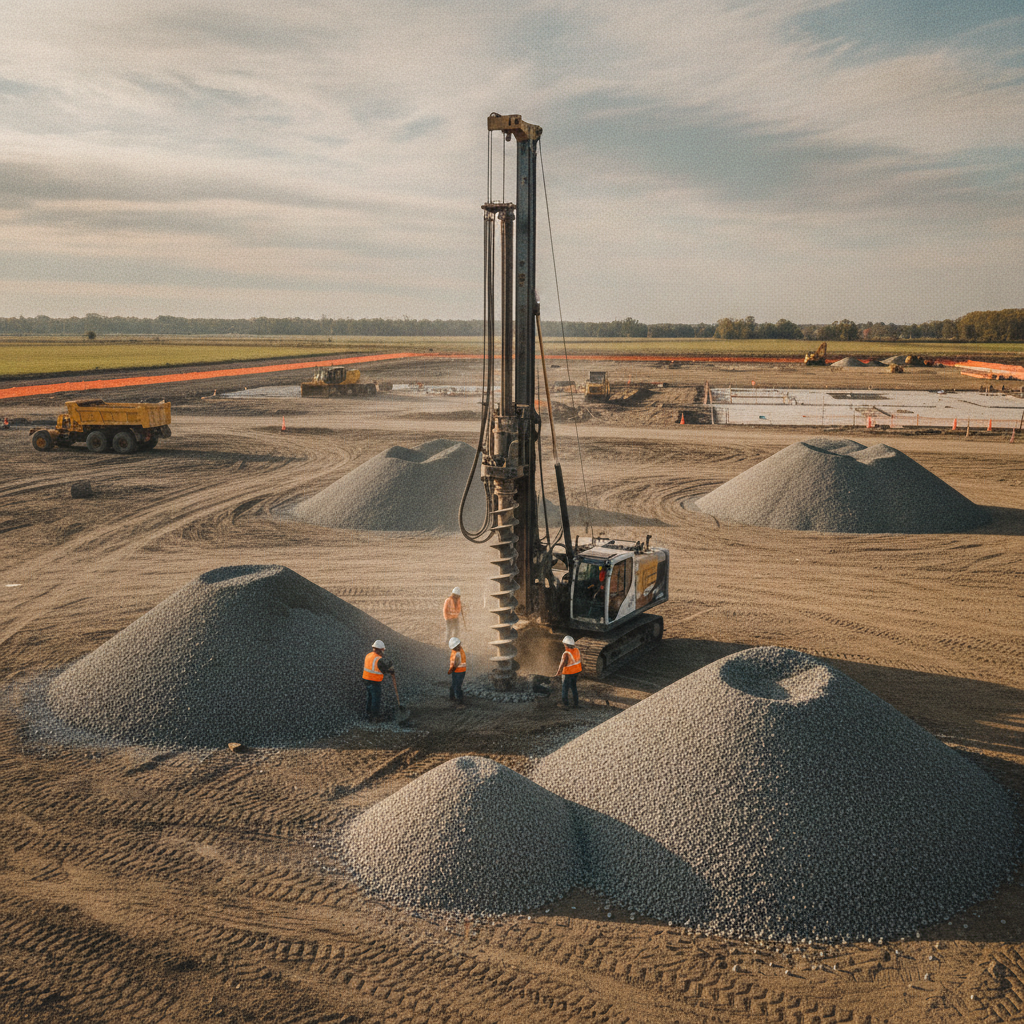
Aggregate piers, often referred to by proprietary names like Geopier® or Rammed Aggregate Piers® (RAPs), are a highly effective method for reinforcing weak, compressible, or otherwise unsuitable soils. The process involves drilling a cavity into the ground, placing lifts of crushed stone (aggregate), and compacting each lift with high-energy vertical ramming. This creates dense, stiff columns of aggregate that significantly increase the soil’s composite bearing capacity and control settlement. RAPs are particularly well-suited for supporting the heavily loaded column footings and mat foundations typical of data centers. They work by creating a composite ground mass that is much stiffer than the surrounding native soil, effectively reducing stress on the weaker soil layers. The installation process is relatively fast and generates minimal spoils, which simplifies site development logistics. A key part of the design involves analyzing the stress distribution between the piers and the matrix soil to ensure settlement remains within the strict tolerances required for data center operations. This technique is a frequent focus of agency review for foundation permits.
Deep Dynamic Compaction (DDC) for Granular Soils
For large sites with deep deposits of loose, granular soils (like sands and gravels), Deep Dynamic Compaction (DDC) can be a cost-effective solution for site-wide improvement. DDC involves repeatedly dropping a very heavy weight (typically 10 to 40 tons) from a significant height (30 to 100 feet) onto the ground surface in a predetermined grid pattern. The high-energy impacts densify the underlying soils, improving their strength and reducing the potential for both settlement and liquefaction. While effective, DDC is a brute-force method that generates significant ground vibration and noise, making it unsuitable for sites with nearby sensitive structures or utilities. The depth of improvement is a function of the weight and drop height, requiring careful calibration by a Geotechnical engineer. Post-treatment testing, such as Cone Penetration Tests (CPT), is essential to verify that the required degree of soil densification has been achieved across the entire site. This method is often considered during the initial phases of large-scale land development before any structures are built.
Vibro-Compaction and Vibro-Replacement (Stone Columns)
Vibroflotation techniques use a large, vibratory probe (a vibroflot) to improve the ground. The specific method depends on the soil type. Vibro-compaction is used in clean, granular soils (sands and gravels). The vibroflot is lowered into the ground, and its powerful vibrations cause the loose soil particles to rearrange into a denser state, increasing the soil’s relative density and mitigating liquefaction risk. In cohesive or mixed soils (like silts and clays), vibro-replacement is used. In this process, the vibroflot creates a hole that is then backfilled with crushed stone. The vibrations compact the stone into a dense, high-modulus column, commonly known as a stone column. These columns serve a dual purpose: they reinforce the soil mass and act as vertical drains to accelerate consolidation settlement. The design and spacing of stone columns are critical elements of the site plan design, ensuring adequate support for the proposed foundation loads.
Grouting Techniques: Compaction, Permeation, and Jet Grouting
Grouting involves injecting fluid materials (grouts) into the ground to fill voids, bind soil particles, or create hardened masses. It is often used for targeted treatment beneath existing structures or in areas with limited access. Compaction Grouting This technique uses a very stiff, low-slump mortar-like grout injected under high pressure to displace and densify the surrounding soil. It is effective for treating sinkhole conditions, densifying loose soils, and even lifting settled foundations. It requires careful monitoring to control the grout placement and prevent unintended ground heave. Permeation Grouting Permeation grouting involves injecting a low-viscosity chemical or microfine cement grout into granular soils. The grout flows into the pore spaces between soil particles and hardens, binding them together to increase strength and reduce permeability. This method is excellent for creating underground barriers or solidifying zones of loose sand without disturbing the soil structure, a key consideration during utility coordination around existing lines. Jet Grouting Jet grouting is a more aggressive technique that uses a high-pressure jet of grout (and sometimes water and air) to erode the native soil and mix it in place with a cementitious slurry. This process creates engineered soil-cement columns called “soilcrete.” Jet grouting is highly versatile and can be used in almost any soil type to provide structural support, control groundwater, or underpin existing foundations. The design of these elements requires a high level of expertise from a Professional Engineer.
Surcharge Loading with Prefabricated Vertical Drains
For sites with thick layers of soft, compressible clays and silts, surcharge loading is a proven method for inducing settlement before construction begins. A large temporary load, typically a mound of soil, is placed over the building footprint. This weight squeezes water out of the compressible soil layers, causing them to consolidate and gain strength. The process can take many months or even years to complete on its own. To accelerate this timeline, Prefabricated Vertical Drains (PVDs), or wick drains, are installed. These are composite plastic strips that are pushed deep into the clay layers. They provide a much shorter path for the water to escape, drastically reducing the time required to achieve the desired degree of consolidation settlement. While effective, this method’s long duration must be factored into the overall site development schedule from day one. It is a common consideration for large land tracts in coastal Florida.
Verification and Quality Control: Ensuring Performance
Ground improvement is not complete once the contractor leaves the site. A rigorous program of verification testing and quality control is mandatory to ensure the improved ground meets the design specifications. This is a critical component of construction administration and is essential for obtaining final approvals. The specific tests depend on the technique used but often include post-treatment in-situ testing to measure the improved soil properties. Common verification methods include Plate Load Tests, which directly measure the bearing capacity and stiffness of the improved ground. Post-treatment Cone Penetration Tests (CPT) and Standard Penetration Tests (SPT) are used to confirm increases in soil density and strength. For aggregate piers, modulus tests are performed on test piers to confirm their stiffness. This data provides the owner and the structural engineer with the confidence that the foundation system will perform as designed for the life of the facility, satisfying all requirements of the Florida Building Code.
RSP Engineers’ Approach to Ground Improvement Strategy
At RSP Engineers, we integrate geotechnical considerations into the earliest stages of project planning. Our process for developing a ground improvement strategy is systematic and data-driven, ensuring a reliable and cost-effective foundation solution for mission-critical projects. We act as the developer’s trusted advisor, managing the complexities from initial investigation through final verification. Our approach begins with a comprehensive Geotechnical Engineering investigation to thoroughly characterize the site’s subsurface conditions. We then perform detailed engineering analyses, modeling various ground improvement options to compare their performance, cost, and schedule implications. Once a technique is selected, we develop detailed design plans and technical specifications for the specialty contractor. Throughout construction, our team provides dedicated Construction Management Services and quality assurance oversight, managing all verification testing and ensuring the work complies with the design intent and all permit requirements.
Common Challenges in Data Center Ground Improvement
Even with careful planning, ground improvement projects can encounter challenges. One of the most common is discovering unexpected subsurface conditions that differ from what was indicated in the initial Soil boring test locations. This can include buried debris, highly variable soil layers, or uncharted utilities, requiring rapid redesign and field adjustments. Another significant challenge is managing the secondary effects of the work, such as ground vibrations from DDC or aggregate pier installation. These must be carefully monitored to avoid damage to adjacent properties or existing infrastructure. Finally, seamless utility coordination and clear communication between the geotechnical specialty contractor, the general contractor, and the civil engineer are paramount. Misaligned schedules or misinterpretations of the design can lead to costly delays and rework, jeopardizing the project’s critical path.
Your Partner for Mission-Critical Site Development
Selecting and designing the right ground improvement strategy is a high-stakes decision that directly impacts your data center’s long-term viability and ROI. Don’t leave it to chance. The team at RSP Engineers provides the expert guidance needed to navigate complex geotechnical challenges. We specialize in comprehensive site engineering services, from initial due diligence and geotechnical coordination to final permitting and construction oversight. Partner with us to ensure your mission-critical facility is built on a foundation of certainty and strength.
Conclusion
For data center developers, the ground beneath their facility is as critical as the servers within it. Ground improvement techniques offer a powerful toolkit for overcoming challenging soil conditions, enabling the use of cost-effective shallow foundations while meeting the world’s most stringent performance criteria. The key to success lies in a thorough geotechnical investigation, a sophisticated engineering analysis to select the right method, and rigorous quality control during construction. By investing in a proper ground improvement strategy, developers can mitigate risk, control costs, and ensure the long-term structural integrity of their vital digital infrastructure, a core component of successful site development.
FAQs
-
The decision depends on several factors, including the soil profile, the magnitude of the structural loads, project schedule, and cost. Ground improvement is often more economical and faster than deep foundations when soil conditions are suitable. A detailed geotechnical investigation and a cost-benefit analysis performed by a Professional Engineer are necessary to make the optimal choice.
-
The schedule impact varies significantly by technique. Rammed Aggregate Piers can often be installed quickly, keeping pace with an aggressive construction schedule. In contrast, surcharge loading with wick drains is a long-duration activity that must be planned months or even a year in advance. The schedule must be integrated into the overall site development plan.
-
Yes, most ground improvement techniques can be adapted for sites with high groundwater. For example, methods like vibro-replacement and jet grouting are performed in saturated conditions. For aggregate piers, techniques may be adjusted to manage groundwater during installation. The high water table is a key design parameter in the drainage design and foundation plan.