
Data Center Generator Foundation Design
A technical guide to data center generator foundation design. Learn about dynamic load analysis, mass concrete, vibration isolation, and utility coordination from Florida’s civil engineering experts a
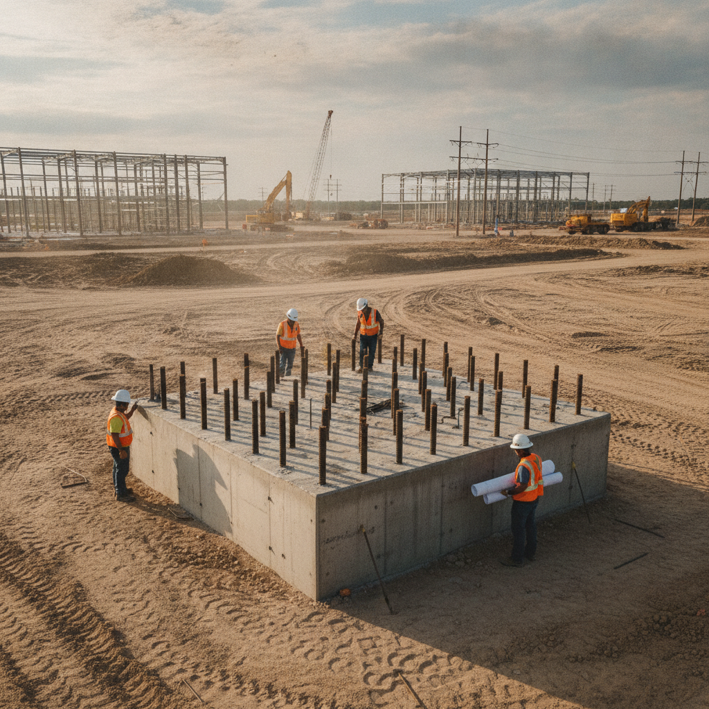
Understanding Static and Dynamic Loads from Industrial Gensets
The first step in foundation design is a thorough load analysis. Generator sets impose two distinct types of loads: static and dynamic. Static loads are straightforward; they include the dead weight of the generator, the engine block, the alternator, the enclosure, and the fuel stored in any sub-base or belly tank. These loads are constant and are used to calculate basic requirements for soil bearing capacity and foundation thickness. The real challenge lies with dynamic loads. These are the vibrational forces generated by the reciprocating motion of the engine’s pistons and rotating components. These forces are cyclical and can induce harmonic vibrations that, if not properly managed, can resonate with the foundation and surrounding soil. A comprehensive geotechnical investigation is essential to understand how the underlying soil will respond to these vibrations. The design must account for various load combinations, including operational vibrations, wind loads, and potential seismic forces, to ensure stability under all conditions.
The Critical Role of Vibration Analysis and Isolation
Generator Foundation Design Parameter Comparison
| Design Parameter | Typical Residential Application (e.g., 20kW Air-Cooled) | Data Center Application (e.g., 2.5MW Diesel) |
|---|---|---|
| Primary Load Consideration | Static Weight | Dynamic Loads & Vibrational Harmonics |
| Vibration Analysis | Generally not required; uses manufacturer-supplied pads. | Mandatory dynamic analysis to prevent resonance. |
| Foundation Type | Small, 4-6 inch thick concrete pad. | Massive reinforced concrete inertia block (often 3-5+ ft thick). |
| Utility Integration | Simple electrical conduit and fuel line stub-up. | Complex network of embedded conduits, fuel piping sleeves, and exhaust blockouts requiring extensive utility coordination. |
| Geotechnical Scrutiny | Visual inspection of subgrade may suffice. | Requires a comprehensive Geotechnical soil report with settlement analysis. |
| Anchorage Requirements | Basic anchors for code compliance. | Engineered anchor bolts designed for high wind and seismic loads. |
| Permitting Complexity | Included with standard building/electrical permit. | Requires detailed structural drawings, potential environmental permits for fuel storage, and rigorous agency review. |
Vibration is the enemy of sensitive equipment and structural longevity. An effective generator foundation must either be massive enough to absorb the vibrational energy (an inertia block) or incorporate a system to isolate it. This requires a detailed dynamic analysis to predict the operating frequencies of the generator and ensure the foundation’s natural frequency is not in resonance. Resonance can amplify vibrations exponentially, leading to premature wear on generator components, cracking in the foundation, and transmission of disruptive vibrations to the main data center building. To prevent this, engineers specify vibration isolators, such as calibrated springs or high-density elastomeric pads, placed between the generator skid and the concrete foundation. These devices are engineered to dampen vibrations at their source, protecting both the equipment and the structure. The selection and specification of these isolators are a critical part of the overall site engineering services and must be coordinated with the generator manufacturer’s requirements.
Mass Concrete Foundations: The Bedrock of Reliability
For large data center generators, the most common solution is a mass concrete foundation, often referred to as an inertia block. The principle is simple: provide enough mass to resist the dynamic forces of the engine and dampen vibrations through sheer weight. The foundation is typically a single, monolithic block of reinforced concrete, often several feet thick, designed to be significantly heavier than the equipment it supports—sometimes by a factor of three to five. The design of the concrete mix, the layout of the steel reinforcement (rebar), and the construction methodology are all critical. The pour must be continuous to avoid cold joints, which could become planes of weakness under vibrational stress. Furthermore, the design must include precise placement of anchor bolts, embedded deep within the concrete, to secure the generator skid and any associated vibration isolators. Proper concrete curing is also vital to achieve the specified compressive strength required for long-term durability.
Coordinating Utilities: Fuel, Exhaust, and Electrical Conduits
A generator foundation is not just a block of concrete; it is a hub of mechanical and electrical systems. A successful design requires meticulous utility coordination long before any concrete is poured. This involves embedding a complex network of conduits and blockouts within the foundation formwork. These pathways accommodate high-voltage electrical cables, control wiring, grounding conductors, and monitoring sensors. Equally important are the provisions for mechanical systems. This includes sleeves or blockouts for large-diameter exhaust piping and penetrations for fuel lines connecting to bulk storage tanks. Any error in the placement of these embedded items can result in expensive and schedule-delaying corrective actions, such as core drilling through reinforced concrete. Effective site plan design integrates these requirements from the outset, using 3D modeling to prevent clashes and ensure all systems fit perfectly.
Seismic and Wind Anchorage for Florida’s Environment
While Florida is not a high-seismic region, building codes still mandate consideration of seismic forces. More pressing for Florida projects are the significant wind loads, especially for generators housed in large, sound-attenuated enclosures. The foundation and its anchorage system must be designed to resist uplift and lateral forces prescribed by the Florida Building Code and ASCE 7. This is achieved through robust anchor bolts that are properly sized, specified for material strength, and have sufficient embedment depth into the concrete foundation. The placement of these anchor bolts is critical and requires the use of precise templates tied securely to the formwork before the concrete pour. Post-installed anchors are generally discouraged for dynamic equipment due to their lower performance under vibrational loads. The entire system—from the enclosure’s connection to the skid, the skid’s connection to the isolators, and the isolators’ connection to the foundation—must be engineered as a complete load path to ensure stability during a hurricane or other extreme weather event.
Subgrade Preparation and Settlement Analysis in the Generator Yard
A massive foundation is useless if the ground beneath it is unstable. The geotechnical soil report is the foundational document for this aspect of the design. It provides critical data on soil type, strength, and compressibility. Based on this report, the civil engineering team will specify the requirements for subgrade preparation. This often includes over-excavation of unsuitable soils, replacement with engineered fill, and compaction to a specified density (typically 95-98% Standard Proctor Density). A key concern is preventing differential settlement, where one part of the foundation settles more than another. This can create stresses on the generator’s rigid frame, leading to misalignment of the engine and alternator shafts and eventual mechanical failure. The geotechnical engineer will perform a settlement analysis to predict long-term soil consolidation under the foundation’s immense weight, ensuring that any settlement is minimal and uniform across the entire pad.
RSP Engineers’ Approach to Generator Foundation Design
At RSP Engineers, we approach mission-critical foundation design with a comprehensive, multi-disciplinary methodology. Our process begins with a detailed review of the generator manufacturer’s specifications and the project’s geotechnical soil report. We collaborate closely with mechanical, electrical, and structural engineers to model all systems in 3D, ensuring seamless utility coordination and eliminating conflicts before construction begins. Our team performs a rigorous structural analysis, accounting for all static, dynamic, wind, and seismic load combinations. This analysis informs the design of the mass concrete foundation, the steel reinforcement, and the critical anchorage systems. We produce detailed construction documents that provide clear guidance for contractors on formwork, rebar placement, anchor bolt templates, and concrete specifications. During construction, we provide construction administration services to verify that the foundation is built exactly as designed, safeguarding the reliability of your critical infrastructure.
Common Issues and Pitfalls in Genset Foundation Projects
Even with careful planning, several issues can arise during the design and construction of generator foundations. A primary pitfall is proceeding without adequate geotechnical data, leading to settlement issues down the line. Another common problem is poor coordination between trades, resulting in misplaced conduits or anchor bolts that require costly and structurally compromising modifications. Overlooking the dynamic properties of the equipment and failing to perform a proper vibration analysis can lead to performance issues that are difficult to remedy after installation. Finally, underestimating the complexity of the permitting process, especially concerning fuel storage and environmental compliance, can cause significant project delays.
Partner with RSP Engineers for Your Mission-Critical Infrastructure
Designing and executing a generator foundation for a data center demands precision, foresight, and deep technical expertise. Mistakes made at this stage can compromise the entire facility’s reliability. The team at RSP Engineers has the experience to navigate these complex challenges. We provide integrated site engineering services, from initial geotechnical analysis and site plan design to detailed structural engineering and construction administration. We ensure your critical infrastructure is built on a foundation of certainty. Contact us today to discuss your project’s specific requirements.
Conclusion: A Foundation for Uninterrupted Operation
In the final analysis, a data center’s generator foundation is far more than just a concrete pad. It is a highly engineered system that is fundamental to ensuring operational continuity. A successful design requires a holistic approach that integrates geotechnical engineering, structural analysis, and meticulous utility coordination. By investing in expert civil engineering from the start, data center developers can mitigate risk, ensure equipment longevity, and build the resilient infrastructure necessary to support our increasingly connected world.
FAQs
-
There is no single answer, as the thickness is engineered for each specific project. It depends on the generator’s total weight, the magnitude of its dynamic loads, the soil’s bearing capacity, and the required mass to act as an effective inertia block. It is common for these foundations to be three to five feet thick, or even more for the largest units.
-
No, they are very different. A housekeeping pad is a thin, slightly raised concrete pad (typically 4 inches) designed to keep equipment clean and dry, away from the main floor slab. A generator foundation is a heavy structural element engineered to support massive loads and resist complex forces, including vibration and wind loads.
-
Absolutely. A geotechnical soil report is non-negotiable for any mission-critical foundation. It provides the essential data needed to determine soil bearing capacity, predict settlement, and design the subgrade. Skipping this step introduces an unacceptable level of risk to the project.