
Data Center Earthwork Specifications
A deep dive into the critical earthwork specifications for data center construction, covering subgrade prep, fill materials, compaction, and quality control. Learn how RSP Engineers ensures a stable f
Initial Site Preparation: Stripping, Grubbing, and Subgrade Proofrolling
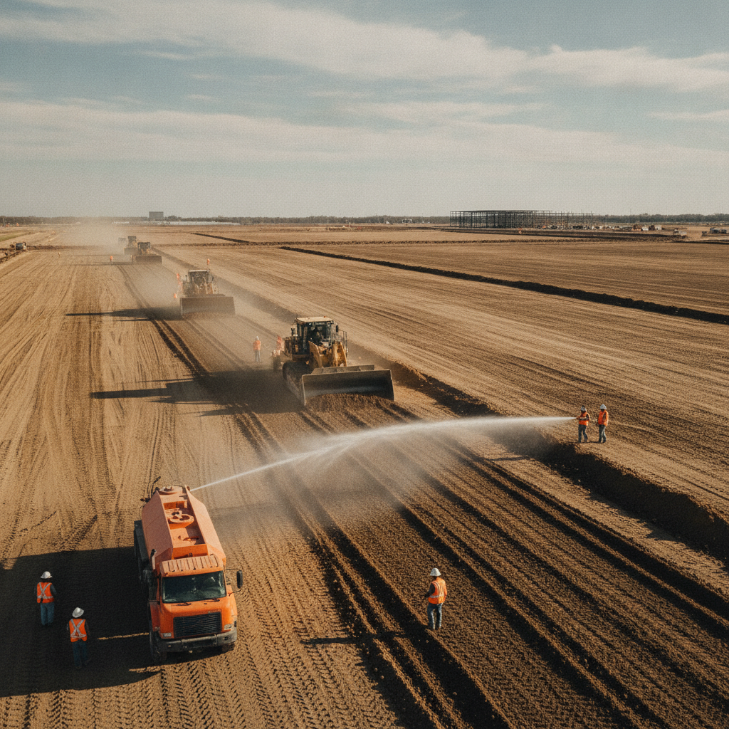
The first physical step in site development is preparing the existing ground. This begins with stripping and grubbing, the process of removing all topsoil, vegetation, roots, and other organic or deleterious materials from the construction footprint. Failing to remove this layer can lead to future decomposition, creating voids and causing settlement under building slabs and pavements. The depth of the strip is determined by the geotechnical soil report, which identifies the extent of the organic-rich topsoil layer. Once the site is stripped to the prescribed subgrade elevation, subgrade proofrolling is performed. This critical quality control step involves driving a heavy, fully-loaded piece of equipment, such as a tandem-axle dump truck or a scraper, over the entire exposed subgrade in a systematic pattern. The purpose is to identify any soft, weak, or unstable areas that deflect, rut, or pump under the load. These areas, which may not have been apparent during the initial geotechnical investigation, must be addressed before any fill can be placed. Proofrolling serves as the final acceptance test of the native ground’s suitability to support the new structure.
Defining Fill Materials: Structural vs. Non-Structural Applications
Data Center Earthwork Compaction and Testing Requirements
| Area of Work | Compaction Requirement (% of Max Dry Density) | Typical Lift Thickness (Loose) | Required Testing Frequency |
|---|---|---|---|
| Building Pad / Slab-on-Grade | 98% (Modified Proctor) | 8 inches | 1 test per 2,500 SF per lift |
| Heavy-Duty Pavement Subgrade (Generator Yards, Loading Docks) | 98% (Modified Proctor) | 8 inches | 1 test per 5,000 SF per lift |
| Utility Trench Backfill (Under Structures/Pavement) | 95% (Standard Proctor) | 12 inches | 1 test per 150 linear feet per lift |
| Exterior Concrete Flatwork (Sidewalks, ADA Ramps) | 95% (Standard Proctor) | 12 inches | 1 test per 10,000 SF per lift |
| Non-Structural Landscape Areas | 90% (Standard Proctor) | 12 inches | As directed by Geotechnical Engineer |
Not all fill is created equal. A key component of any earthwork specification is the clear distinction between structural fill and non-structural fill. Structural fill is any material placed beneath building foundations, floor slabs, roadways, parking lots, and other load-bearing structures. It must meet stringent requirements for strength, stability, and low compressibility. In contrast, non-structural fill is used in landscape areas, berms, or other zones where settlement is not a critical concern. The specifications for structural fill are far more rigorous. They dictate the allowable material types, often requiring clean sands, sand-clays, or crushed rock with specific properties. The goal is to create a predictable, homogenous, and strong foundation layer. Using non-structural fill in a structural area is a recipe for failure. Clear definitions in the construction documents, supported by a comprehensive site plan design, prevent ambiguity and ensure the contractor uses the correct materials in the appropriate locations, which is a core responsibility of Civil Engineers.
Material Specifications: Gradation, Plasticity, and Proctor Testing
The suitability of a soil for use as structural fill is defined by its physical properties. A geotechnical engineer will establish these criteria based on laboratory testing. Key specifications include material gradation and plasticity. Gradation, determined by a sieve analysis, refers to the distribution of particle sizes within the soil. A well-graded material has a good mix of particle sizes, which allows for better compaction and stability. Poorly graded soils, like uniform fine sands, can be less stable. Plasticity is a measure of a soil’s behavior with varying moisture content, particularly for soils containing clays and silts. The Atterberg Limits tests determine the Liquid Limit and Plastic Limit, and the difference between them is the Plasticity Index (PI). Soils with a high PI are highly plastic, meaning they swell when wet and shrink when dry, making them unsuitable for structural fill. Specifications will typically cap the maximum allowable PI. Finally, the Proctor Test (either Standard or Modified) is performed in the lab to determine a soil’s maximum dry density and its corresponding optimal moisture content, which become the benchmark for field compaction testing.
The Art of Placement: Lift Thickness and Moisture Conditioning
Achieving proper compaction is impossible without correct placement procedures. Fill material cannot be simply dumped and spread; it must be placed in controlled layers known as lifts. The specification will define the maximum allowable lift thickness, typically 8 to 12 inches in a loose state before compaction. Thicker lifts prevent the compactive energy from reaching the bottom of the layer, resulting in a dense top crust over a weak, under-compacted base. Equally important is moisture conditioning. The Proctor Test identifies the ideal moisture content at which a soil can achieve its greatest density. In the field, the contractor must adjust the soil’s moisture to be within a specified range of this optimum, usually ± 2-3%. This may involve adding water with a water truck if the soil is too dry or aerating it with a disc harrow if it is too wet. Proper moisture conditioning is essential for meeting the stringent compaction requirements demanded by data center projects.
Compaction Requirements and Quality Control Testing
The core of earthwork quality control is verifying that the specified density is achieved in the field. Compaction requirements are expressed as a percentage of the maximum dry density determined by the Proctor test. For a data center, these are typically very high: 98% for building pads and pavement subgrades, 95% for utility trench backfill under structures, and 90-92% for landscape areas. These values ensure minimal future settlement under heavy static and dynamic loads. Verification is performed by a third-party testing agency, overseen by a Geotechnical engineer. The most common method is the nuclear density gauge, which provides rapid, real-time measurements of in-place density and moisture content. The testing frequency is also specified, for example, one test per 2,500 square feet per lift in a building pad. This rigorous construction administration and testing protocol provides documented proof that the earthwork meets the project’s engineering standards.
Managing Site Challenges: Undercutting and Unsuitable Materials
Despite the most thorough geotechnical investigation, unforeseen conditions can arise. When proofrolling identifies a soft spot, the solution is typically to undercut the area. This involves excavating the weak or unsuitable material until competent soil is reached and backfilling the excavation with engineered structural fill, placed and compacted in lifts. Unsuitable materials can include organic soils, high-plasticity clays, debris, or overly wet soils that cannot be stabilized. Handling undercuts can significantly impact project costs and schedules, especially on large sites. A well-written specification will anticipate this by including clear definitions of what constitutes unsuitable material and establishing unit prices for its removal and replacement. This proactive approach, a hallmark of experienced Licensed Engineers, transforms a potential dispute and change order into a manageable, pre-defined process, protecting the owner’s budget and timeline.
RSP Engineers’ Approach to Earthwork Specification and Management
At RSP Engineers, we recognize that a successful data center project is built from the ground up. Our process for managing earthwork is comprehensive and proactive, designed to mitigate risk and ensure performance. It begins with a meticulous review of the project-specific geotechnical soil report to understand the site’s opportunities and constraints. We then integrate these findings directly into our site plan design, optimizing grading to achieve a cut/fill balance where possible and minimizing the costly import or export of materials. Our team develops clear, enforceable technical specifications that leave no room for ambiguity. We define material properties, placement methods, and quality control standards in detail. During construction, we provide diligent construction administration, acting as the owner’s representative. We collaborate closely with the contractor and the third-party testing agency to review test results, troubleshoot field issues like unexpected unsuitable materials, and ensure every lift of fill meets the stringent requirements for your mission-critical facility.
Common Pitfalls in Data Center Earthwork
Even with a solid plan, several common issues can derail an earthwork program. An insufficient geotechnical investigation is a primary culprit, leading to costly surprises once construction begins. Vague specifications are another major risk, creating disputes over what constitutes acceptable fill or necessary undercutting. Poor field control of moisture content is a frequent cause of failed compaction tests, leading to rework and delays. Contractors sometimes attempt to place lifts that are too thick to save time, compromising the quality of the entire fill mass. Finally, underestimating the impact of weather, especially intense rain events, can saturate soils and bring operations to a halt if not properly managed through effective stormwater management on the active construction site.
Partner with RSP Engineers for Your Mission-Critical Site Development
Your data center investment is too valuable to rest on an uncertain foundation. Achieving the required performance demands engineering precision from the very start. The team at RSP Engineers provides the expert site engineering services needed to navigate the complexities of large-scale earthwork. We deliver clear specifications, proactive construction administration, and a deep understanding of geotechnical engineering principles to ensure your project is built on solid ground. Contact us to discuss how we can support your next mission-critical development.
A Solid Foundation is Non-Negotiable
In conclusion, the technical specifications governing data center earthwork are a critical component of risk management and long-term asset protection. From subgrade proofrolling and material selection to moisture conditioning and rigorous compaction requirements, every step is designed to create a stable, predictable, and resilient foundation. Investing in a thorough geotechnical investigation and partnering with an experienced civil engineering firm to develop and enforce these specifications is essential. This diligence in the initial site development phase prevents costly change orders, construction delays, and the far greater cost of future structural problems.
FAQs
-
Data centers have extremely heavy floor loads from servers, batteries, and cooling equipment, and the equipment itself is highly sensitive to vibration and movement. Even minor differential settlement can damage infrastructure and cause downtime. Therefore, the earthwork must create an exceptionally stable and uniform foundation with near-zero potential for future movement. What is the role of the geotechnical engineer vs.
-
The Geotechnical engineer investigates the subsurface soil and rock conditions, performs laboratory tests, and provides recommendations for site preparation, fill materials, and foundation design in a geotechnical soil report. The civil engineer takes that information and incorporates it into the overall site plan design, creating the grading plans, utility layouts, and the detailed construction specifications the contractor will follow.
-
A high water table can saturate subgrade soils, making them unstable and difficult to compact. It often requires active dewatering during excavation and fill placement. It also influences the selection of fill material, as some soils lose strength when saturated. The drainage design for the finished site is also critical to keep groundwater from compromising the building foundation and pavement subgrades over the long term.