
Transformer Foundation Design for Data Center Substations
Explore the critical civil and structural engineering requirements for data center transformer foundations, including geotechnical analysis, oil containment, grounding, and seismic design.
Foundational Loads and Geotechnical Considerations
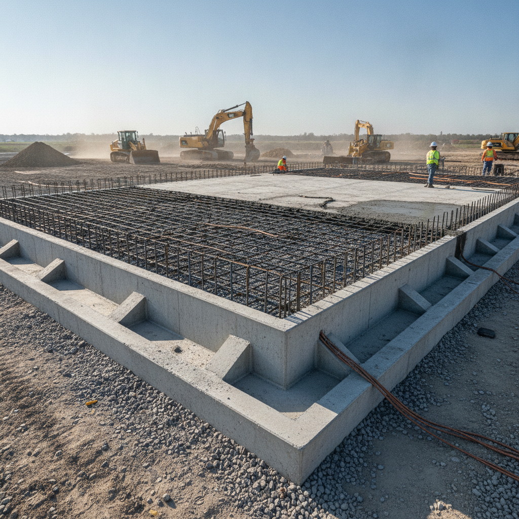
Large power transformers used in data center substations can weigh hundreds of thousands of pounds. The foundation must safely transfer this massive static load to the underlying soil without unacceptable settlement. The process begins with a thorough Geotechnical Engineering investigation, including soil boring test procedures to understand the subsurface conditions. The resulting Geotechnical soil report provides critical data on soil bearing capacity, potential for consolidation, and the presence of groundwater, which directly informs the foundation design. Beyond the static weight, the design must account for dynamic and temporary loads. This includes operational vibrations and, critically, the concentrated loads imposed during installation. Transformers are often moved into place using rollers or hydraulic jacks, which can exert immense pressure on small areas of the foundation. The structural design, led by a licensed Professional Engineer, must include reinforcement and concrete thickness sufficient to handle these installation stresses. Failure to account for these loads can lead to cracking or structural failure before the transformer is even energized.
Integrated Oil Containment and Environmental Compliance
Key Design Parameters for Transformer Foundations
| Design Parameter | Single-Unit Pad Consideration | Multi-Unit Substation Consideration |
|---|---|---|
| Geotechnical Analysis | Focus on uniform bearing capacity and settlement control for a single, heavy load. A Geotechnical soil report is essential. | Analyze potential for differential settlement between multiple heavy foundations, which could stress buswork and connections. |
| Oil Containment Strategy | Typically an integrated curb or a simple sloped pad draining to a collection point. Volume is based on one unit. | May require a complex shared system with oil-water separators and diversion valves to isolate spills from a specific unit. |
| Grounding Integration | Grounding conductors are bonded to the foundation rebar and connected to the main site grid. | The foundation grounding becomes an integral part of a larger, more complex substation grounding grid designed to manage higher fault currents. |
| Seismic/Wind Restraint | Anchorage is designed for the specific mass and geometry of the single transformer. | Design must consider potential interaction between units and the structures supporting interconnecting buswork during a seismic event. |
| Future Replacement Access | A clear pull-path for removal and delivery is required. Laydown area must be planned. | Complex logistics are needed to replace one unit without de-energizing or endangering adjacent live equipment. Requires carefully planned corridors. |
Most large power transformers are filled with thousands of gallons of mineral oil for cooling and insulation. A leak or rupture could result in a significant environmental hazard. Consequently, federal regulations, such as the Spill Prevention, Control, and Countermeasure (SPCC) rule, mandate secondary containment systems. For transformer pads, this is typically achieved by integrating a containment basin directly into the foundation design. This can be a raised concrete curb forming a “bathtub” around the transformer or a sloped pad that directs spills to a dedicated collection point or an oil-water separator. The design of the containment system is a critical aspect of the civil engineering scope. The required volume must typically hold the entire oil volume of the largest transformer plus a margin for precipitation from a significant storm event. Containment volume requirements and design standards vary by jurisdiction, and every project team should confirm the applicable standards with the local, state, regional, and federal authorities that hold review authority over the site. Proper permitting and documentation are essential to demonstrate compliance and avoid regulatory penalties.
Grounding Grid and Electrical System Integration
Electrical safety within a substation is paramount, and a key component is the grounding grid. This is a network of buried copper conductors that creates an equipotential plane to protect personnel from hazardous step and touch potentials during a fault condition. The transformer foundation design must be meticulously coordinated with the electrical engineer’s grounding grid design. Often, grounding conductors are cast directly into the foundation’s concrete mat or placed in trenches directly beneath it, bonding with the rebar and anchor bolts. This integration requires precise planning during the site plan design phase. The location of grounding risers, connections to the transformer tank, and pathways for main grounding conductors must be clearly detailed in the construction documents. Poor coordination can lead to costly rework, compromised electrical safety, and delays in commissioning the substation. Effective utility coordination between the civil, structural, and electrical teams is essential for a successful outcome.
Seismic and Wind Load Anchorage and Restraint
In many parts of the country, substations must be designed to withstand significant seismic activity or high wind loads. For a top-heavy piece of equipment like a transformer, the forces generated during such an event can be immense. The foundation and anchorage system are the primary defense against the transformer sliding, overturning, or suffering damage that could cause a catastrophic failure and power outage. The structural engineer of record is responsible for this critical aspect of the site engineering services. The design involves calculating the lateral and uplift forces based on the project’s location and the applicable building codes, such as ASCE 7. Heavy-duty anchor bolts are embedded deep into the concrete foundation to secure the transformer. In high-seismic areas, additional restraints or specialized energy-dissipating anchorages may be required. The structural engineering analysis must be robust, ensuring the foundation has sufficient mass and the anchorage has adequate strength to resist the worst-case design loads.
Cable Trench and Duct Bank Interface Design
A transformer is the nexus of numerous high-voltage and control cables. These cables are routed through underground duct banks and cable trenches that must interface directly with the foundation. The civil engineering design must precisely locate and detail these penetrations. This often involves creating blockouts or embedding sleeves in the foundation formwork before the concrete is poured. These openings must be perfectly aligned with the incoming and outgoing duct bank routes. Coordination is critical to avoid conflicts with structural reinforcing steel and to ensure proper sealing around penetrations to prevent water intrusion. Waterstops are often cast into the concrete around sleeves and blockouts to create a watertight seal. A failure in this detailed design work can result in having to core-drill the foundation later—a costly, time-consuming, and structurally undesirable process. This highlights the importance of integrated site development plans that show all underground utilities in three dimensions.
Designing for Maintenance and Future Replacement
A transformer foundation’s design life should match or exceed that of the equipment it supports, but transformers do eventually need to be replaced. A forward-thinking design accounts for this from day one. The civil engineering plans must incorporate a clear, unobstructed, and structurally adequate access path for the heavy transport vehicle that will deliver the new unit and remove the old one. This is often called a “pull-path” or “haul route.” The area around the foundation must also be designed to accommodate the replacement process, which may involve jacking and sliding the unit or using a large crane. This requires sufficient laydown area and ground stable enough to support the crane and its outriggers. In a multi-unit substation, this planning is even more critical to ensure a replacement can occur safely without requiring a complete shutdown of the facility. This level of planning is a hallmark of experienced construction administration and design.
RSP Engineers’ Approach to Substation Foundation Design
At RSP Engineers, we approach transformer foundation design as a critical, multi-disciplinary task central to project success. Our process begins with a deep dive into the project’s specific needs, including the transformer specifications and the site’s geotechnical and environmental conditions. We lead the coordination between our Civil Engineers, the structural engineer of record, and the electrical design team to produce a fully integrated design. Our deliverables include a comprehensive site plan design that details not only the foundation itself but also the surrounding grading, drainage, access routes, and utility interfaces. We focus on creating constructible, compliant, and resilient designs that minimize risk and provide long-term value. Our experience with permitting and agency review processes across the country helps streamline approvals for mission-critical infrastructure projects.
Common Issues and Design Oversights
Several common oversights can compromise a transformer foundation project. The most frequent is an inadequate Geotechnical Engineering investigation, which can lead to costly foundation settlement and equipment misalignment. Another common issue is poor coordination of underground utilities, resulting in duct banks conflicting with foundation footings or rebar. Undersizing the oil containment volume or failing to account for storm water inflow is a frequent compliance misstep. Perhaps the most challenging issue to fix later is the failure to plan for future replacement. A foundation built without a clear access path can turn a future transformer swap into an enormously expensive and disruptive logistical nightmare. These issues underscore the need for experienced Civil Engineering firms that understand the full lifecycle of data center infrastructure.
Partner with RSP Engineers for Your Mission-Critical Infrastructure
A data center’s success depends on the flawless performance of its power infrastructure. Ensuring that infrastructure is built on a solid, compliant, and resilient foundation requires specialized expertise. The team at RSP Engineers provides the comprehensive site engineering services needed to navigate these complex projects. From initial due diligence and Geotechnical Engineering coordination to detailed utility coordination and final permitting, we deliver designs that stand the test of time. Don’t let an overlooked foundation detail become a critical point of failure. Contact RSP Engineers today to discuss how our experienced team can support your next mission-critical site development project.
Conclusion
The design of a transformer foundation for a data center substation is a complex engineering challenge that sits at the intersection of geotechnical, civil, structural, and electrical disciplines. It demands meticulous planning to manage extreme loads, ensure environmental compliance, provide electrical safety, and plan for the equipment’s entire lifecycle. A successful design is the result of a holistic civil engineering approach that prioritizes integration and foresight. By addressing these critical design considerations upfront, data center developers can mitigate risks, avoid costly construction errors, and build the reliable power infrastructure necessary to support the digital world. Ultimately, a well-designed foundation is a long-term investment in the operational resilience of any mission-critical facility.
FAQs
-
The most critical first step is commissioning a comprehensive Geotechnical soil report. This report, based on site-specific Soil Test data, provides the essential soil bearing capacity and settlement information that dictates the entire structural design of the foundation.
-
Typically, the containment system must be sized to hold 100% of the oil volume from the largest single transformer, plus an additional volume to account for precipitation from a design storm (e. g. , a 24-hour, 25-year storm event). However, specific requirements for freeboard and rainfall calculations can vary significantly by jurisdiction and must be confirmed with the local authority.
-
Coordination is critical for personnel safety. An improperly designed or installed grounding system can fail to control dangerous step and touch voltages during an electrical fault, posing a lethal risk. Integrating the grid with the transformer foundation rebar helps create a robust equipotential plane.