
Force Main Design for Data Center Wastewater Systems
Explore the critical civil engineering principles of force main design for data center wastewater systems, including pipe sizing, material selection, surge analysis, and permitting.
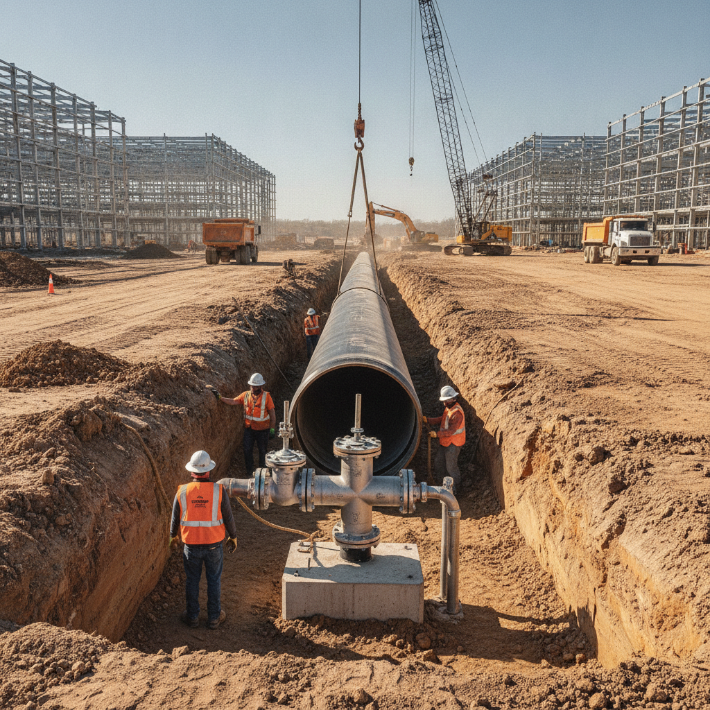
Sizing for Optimal Flow Velocity and Head Loss
The fundamental goal of force main design is to transport wastewater without allowing solids to settle and without creating excessive pressure and energy consumption. This is achieved by carefully sizing the pipe diameter to maintain a specific flow velocity. The target is typically a self-scouring velocity, usually between 2 and 5 feet per second (fps), which is fast enough to keep suspended solids from depositing and causing blockages. Velocities below 2 fps risk sediment buildup, while velocities above 8-10 fps can lead to high friction losses, potential pipe erosion, and significant energy costs for the lift station pumps. Calculating the required pressure, or Total Dynamic Head (TDH), is a core task for the Civil Engineer near me. This calculation considers the static head (the vertical distance the wastewater must be lifted) and the dynamic head (the friction losses within the pipe and losses from fittings like bends and valves). Engineers use established hydraulic equations, such as the Hazen-Williams or Darcy-Weisbach formulas, to model these friction losses accurately. This hydraulic modeling ensures the selected pumps have the proper performance curve to overcome the TDH and deliver the design flow rate efficiently throughout the system’s life.
Pipe Material Selection and Pressure Classification
Force Main Pipe Material Comparison for Data Center Applications
| Material | Key Advantages | Design Considerations | Typical Applications |
|---|---|---|---|
| PVC (Polyvinyl Chloride) | Cost-effective, high corrosion resistance, smooth interior for low friction loss, widely available. | Can be brittle in cold weather, requires careful bedding and backfill, bell-and-spigot joints require thrust restraint. | Standard municipal and commercial applications with moderate pressures and stable soil conditions. |
| HDPE (High-Density Polyethylene) | Highly flexible, fused joints are leak-proof and self-restraining, excellent chemical resistance, suitable for trenchless installation (HDD). | Lower pressure rating per wall thickness compared to DIP, requires specialized fusion equipment for jointing. | Projects requiring directional drilling, crossing sensitive areas, or in corrosive soil environments. |
| DIP (Ductile Iron Pipe) | Very high strength and pressure ratings, durable and resistant to physical damage during installation. | Heavier and more difficult to handle, requires interior and exterior coatings for corrosion protection, especially against H2S. | High-pressure systems, areas with heavy surface loads (e.g., under roadways), and connections to existing iron pipe networks. |
| Fiberglass Reinforced Pipe (FRP) | Extremely high corrosion resistance, lightweight, very smooth interior surface. | Higher initial material cost, requires specialized installation expertise and handling to prevent damage. | Highly corrosive environments, such as industrial wastewater or coastal areas with aggressive soils. |
| Steel Pipe | Highest pressure capabilities, can be fabricated in large diameters, very strong. | Susceptible to both internal and external corrosion, requiring robust coatings and cathodic protection systems. | Very high-pressure transmission mains, aerial crossings, and specialized industrial or power plant applications. |
Choosing the right pipe material is critical for the longevity and reliability of a force main. Common materials include Polyvinyl Chloride (PVC), High-Density Polyethylene (HDPE), and Ductile Iron Pipe (DIP). Each has distinct advantages regarding cost, installation methods, and corrosion resistance. For instance, HDPE is often preferred for its flexibility and fused, leak-free joints, making it ideal for trenchless installation methods. DIP offers high strength and durability, while PVC provides a cost-effective and widely accepted solution for many applications. The selection process involves evaluating the project’s specific needs, including operating pressures, external loads, and the chemical composition of the wastewater. Equally important is selecting the correct pressure class or rating for the pipe. This rating must be sufficient to handle the maximum anticipated pressure, which includes the normal operating pressure from the pumps plus any potential surge pressures from events like a sudden pump shutdown. Design standards and material specifications for public utilities vary by jurisdiction, and every project team should confirm the applicable standards with the local, state, regional, and federal authorities that hold review authority over the site. A thorough permitting strategy involves early coordination with the receiving utility to ensure all material and design standards are met, preventing costly redesigns during agency review.
Profile Design and Air Release Valve Placement
A force main rarely follows a perfectly flat or consistently sloped path. Its vertical profile, which tracks the pipe’s elevation along its route, is a critical design consideration. High points in the pipeline can trap air that comes out of the solution, forming pockets that restrict flow, increase pumping head, and can even cause a complete flow stoppage. To prevent this, civil engineers strategically place Air Release Valves (ARVs) at all high points identified in the profile analysis. These mechanical valves automatically vent accumulated air when the system is under pressure. Conversely, combination air/vacuum valves are also placed at high points to allow large volumes of air to enter the pipe during draining or a line break, preventing a vacuum from forming that could collapse the pipe. The proper specification and placement of these valves are essential for the hydraulic efficiency and structural integrity of the force main. A detailed profile view on the site plan design drawings is a standard deliverable, clearly showing pipe elevations, slopes, and the precise location of every ARV.
Surge and Water Hammer Analysis
One of the most significant risks in a pressurized pipeline is hydraulic surge, commonly known as water hammer. This phenomenon occurs when the velocity of the fluid changes rapidly, such as during a sudden pump startup or, more critically, a power failure that causes an abrupt pump shutdown. The moving column of water slams to a halt, creating intense pressure waves that travel back and forth through the pipe. These surge pressures can be many times the normal operating pressure and can easily rupture pipes, damage valves, and destroy pump equipment. For data centers, where uptime is paramount, such a failure is unacceptable. For long or high-head force mains, a formal surge analysis is a crucial part of the design process. This is a specialized computer modeling exercise that simulates pressure transients under various operating scenarios. Based on the analysis, engineers can design mitigation measures to control surge pressures within the pipe’s rated capacity. Common solutions include variable frequency drives (VFDs) for soft pump starts and stops, surge tanks, pressure relief valves, or specially designed check valves. This analysis is a hallmark of diligent site engineering services and protects the owner’s investment.
Provisions for Maintenance: Cleanouts and Pigging
A force main is a buried asset that must be designed for long-term maintenance. Over time, grease and solids can accumulate on the pipe walls, reducing its effective diameter and increasing friction losses. To manage this, the design must include access points for cleaning and inspection. For smaller diameter force mains, cleanouts may be installed at strategic locations, similar to those in gravity sewer systems, allowing for flushing and maintenance access. For larger and longer force mains, particularly those critical to a data center’s operation, provisions for pigging are often included. Pigging involves launching a polyurethane device—the “pig”—into the pipeline and using system pressure to push it through to a receiving station. The pig scrapes the inside of the pipe, removing buildup and restoring hydraulic capacity. A piggable design requires specialized launching and receiving stations, long-radius bends, and full-port valves that do not obstruct the pig’s passage. This foresight during the site development phase ensures the system remains efficient for decades.
Discharge Manhole Design and Corrosion Control
The point where the force main terminates and discharges into a gravity sewer manhole is a zone of high turbulence and chemical activity. As the pressurized flow enters the manhole, dissolved gases—most notably hydrogen sulfide (H2S)—are released into the manhole atmosphere. When H2S gas mixes with moisture, it forms sulfuric acid, which is extremely corrosive to standard concrete. Without proper protection, a standard manhole can be destroyed in a matter of years, leading to structural failure and a sanitary sewer overflow. Effective drainage design for the discharge point is therefore critical. The design should minimize turbulence, often by using a drop connection that introduces the flow below the water level in the manhole. Furthermore, the manhole itself must be protected. This is typically achieved by specifying a corrosion-resistant interior lining, such as a cast-in-place PVC liner, an epoxy coating, or by constructing the manhole from a non-corrosive material like fiberglass. This is a key detail that experienced Civil Engineering firms will not overlook during the design and permitting process.
The RSP Engineers Approach to Force Main Design
At RSP Engineers, our process for designing mission-critical utility infrastructure is comprehensive and collaborative. We understand that a force main is a key component of a data center’s operational continuity. Initial Feasibility & Utility Coordination: We begin by analyzing the site topography and coordinating with the receiving municipal utility to establish connection points, design standards, and permitting requirements. Detailed Hydraulic Modeling: Our team performs detailed hydraulic calculations and, when necessary, a full surge analysis to ensure the system is sized correctly, pumps are selected appropriately, and pressures are controlled. Material & Component Specification: We select the most appropriate pipe materials, valves, and corrosion protection systems based on the project’s specific technical requirements and budget, ensuring long-term durability. Agency Permitting & Approvals: We prepare and manage the complete permit submittal package, navigating the review process with local and state agencies to secure timely approvals for the site plan design. Construction Administration & Testing: We provide support throughout construction, reviewing submittals, observing installation, and overseeing critical testing procedures like pressure and leakage tests to ensure the final installation meets the design intent.
Common Pitfalls in Force Main Projects
Even with a solid design, force main projects can encounter issues if details are overlooked. Some common pitfalls include underestimating surge pressures, leading to catastrophic failure; improper placement or specification of air release valves, causing chronic operational problems; neglecting corrosion protection at the discharge manhole, resulting in premature structural failure; poor coordination between the civil design and the lift station’s electrical and controls design; and failing to account for future expansion of the data center campus, leading to an undersized system.
Partner with RSP Engineers for Your Data Center Utility Infrastructure
Designing and permitting a force main for a mission-critical facility requires specialized expertise. The team at RSP Engineers has a deep understanding of the hydraulic, material, and regulatory challenges involved. We provide comprehensive site engineering services, from initial feasibility studies and utility coordination to detailed design, permitting, and construction administration. Ensure your data center’s foundational infrastructure is designed for reliability and longevity. Contact us today to discuss your project’s wastewater management needs.
Conclusion
A well-designed force main is an invisible but indispensable asset for any data center that cannot connect to a gravity sewer. Success lies in a holistic civil engineering approach that balances hydraulic efficiency, material durability, surge protection, and long-term maintainability. From precise velocity calculations to robust corrosion control at the discharge, every detail matters. Partnering with experienced Civil Engineers who understand the nuances of site development for mission-critical facilities is the best way to ensure this vital piece of infrastructure performs reliably for the life of your data center.
FAQs
-
The generally accepted minimum scouring velocity is 2. 0 feet per second (fps). This velocity is required to keep organic solids suspended in the flow, preventing them from settling in the pipe and causing blockages or septic conditions. The final design velocity is a balance between achieving scouring velocity and minimizing friction loss.
-
The pressure class is determined by the maximum anticipated pressure the pipe will experience. This includes the highest operating pressure generated by the lift station pumps (the shutoff head) plus the maximum calculated surge pressure that could occur during an event like an emergency power failure. A factor of safety is then applied to select the final pipe pressure class.
-
A surge analysis, or transient analysis, is crucial for long or high-pressure force mains to model the effects of water hammer. It predicts the extreme high and low pressures that occur during sudden changes in flow. Without this analysis, a design might not include necessary protective measures, putting the pipeline at risk of rupture or collapse. It is a key part of responsible utility design.