
Data Center Stormwater Outfall Design
A technical guide for data center developers on stormwater outfall design in Florida. Learn about outlet protection, rip-rap, permitting, and channel stability from RSP Engineers.
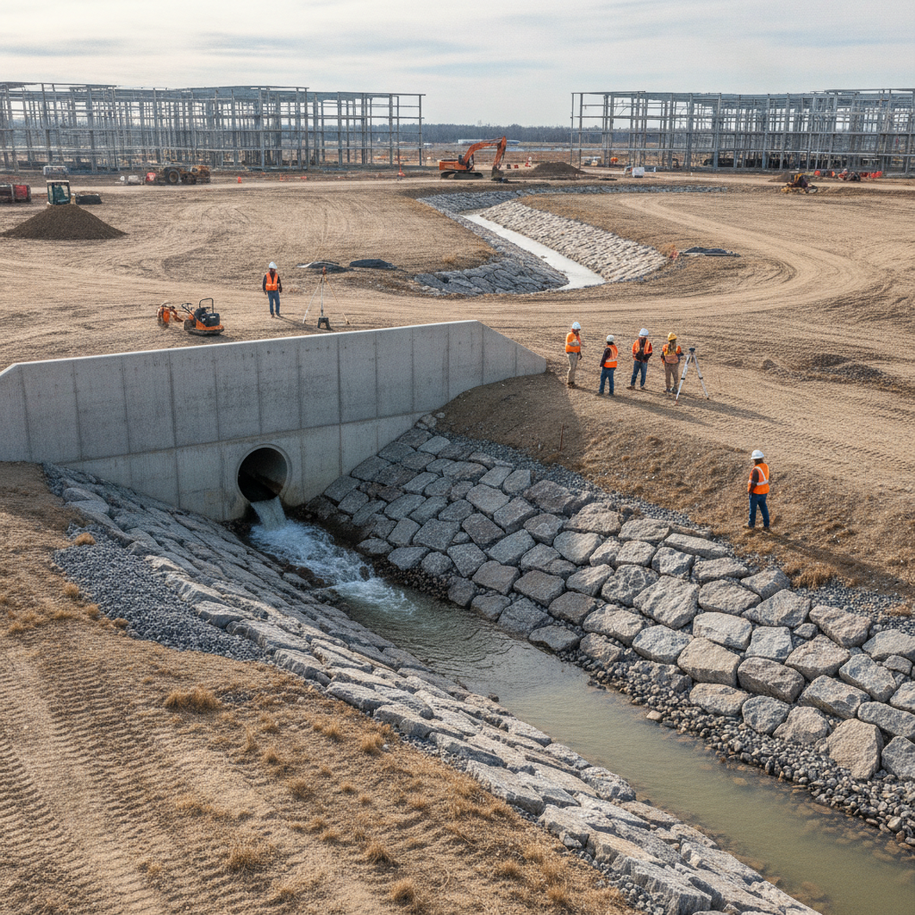
The Role of Outlet Protection and Energy Dissipation
Water discharged from a pipe is concentrated and travels at a higher velocity than natural sheet flow. Releasing this high-energy flow directly onto an unprotected surface will inevitably cause erosion, or scour. The primary goal of an outfall structure is to provide outlet protection by dissipating this energy, reducing the water’s velocity to a non-erosive level before it enters the receiving channel. This process is known as energy dissipation, and it is a fundamental principle of hydraulic engineering. The selection of an appropriate energy dissipator depends on the calculated outlet velocity, the size of the discharge pipe, and the characteristics of the downstream channel. Common methods range from simple rip-rap aprons for lower-velocity flows to more complex engineered structures like baffled outlets or stilling basins for high-energy discharges. The design must be robust enough to handle the peak flow rate from a design storm event, as specified by the governing Water Management District and local municipal code. Neglecting proper energy dissipation is one of the most common causes of outfall failure and subsequent environmental damage.
Sizing and Specifying Rip-Rap Aprons for Scour Protection
Outfall Component Selection Based on Site Conditions
| Component | Primary Function | Typical Application / Design Driver | Key Florida Permitting Consideration |
|---|---|---|---|
| Rip-Rap Apron | Energy dissipation and scour protection | Low to moderate velocity outfalls (typically < 10 ft/s). Driven by pipe size and exit velocity. | Must meet FDOT or WMD standards for stone size (D50), thickness, and geotextile underlayment. |
| Concrete Headwall with Wingwalls | Structural support and embankment retention | Larger pipes (>36"), steep embankments, or where flow needs to be directed. | Structural calculations may be required. Ensures a stable, non-erosive transition point. |
| Flared End Section (FES) | Hydraulic efficiency and minor scour reduction | Smaller diameter pipes on relatively flat slopes where a full headwall is not required. | Demonstrate that it provides adequate protection for the calculated exit velocity. |
| Engineered Stilling Basin | High-level energy dissipation | High-velocity, high-volume discharges where a rip-rap apron is insufficient. Common for large regional ponds. | Requires complex hydraulic modeling and detailed design to prove effectiveness to the reviewing agency. |
| Vegetated/Reinforced Channel | Conveyance and downstream stability | The receiving channel itself. May require turf reinforcement matting (TRM) or other stabilization methods. | Downstream analysis must prove the channel is stable for post-development flow rates and velocities. |
For many data center projects in Florida, a well-designed rip-rap apron is the most common and cost-effective method for outlet protection. This engineered layer of angular stone armor is placed at the pipe outlet to absorb the impact of the concentrated flow, slowing it down and spreading it out. The sizing of the apron is not arbitrary; it is a calculated process based on hydraulic principles outlined in resources like the Florida Department of Transportation (FDOT) Drainage Manual. Key inputs for sizing a rip-rap apron include the pipe’s diameter, the peak discharge velocity, and the tailwater depth. These factors determine the required median stone diameter (D50), the thickness of the stone layer, and the overall length and width of the apron. Equally important is the specification of a non-woven geotextile fabric to be placed beneath the rip-rap. This fabric prevents the underlying soil from being washed away through the voids in the stone, which would cause the apron to settle and fail. A proper drainage design ensures these specifications are clearly detailed in the construction plans.
Headwalls, Endwalls, and End Sections: Structural Integrity at the Discharge Point
The transition from the stormwater pipe to the open environment requires a structurally sound interface. This is typically achieved with a concrete headwall, endwall, or a manufactured end section. A headwall is a vertical concrete wall at the end of a pipe that retains the surrounding earth embankment, provides a stable connection point, and prevents erosion around the pipe. For larger pipes or outfalls in sloped areas, wingwalls may be added, flaring out from the headwall to provide additional embankment stability and smoothly guide flow into the channel. Precast concrete structures are often used for efficiency, but cast-in-place solutions may be necessary for custom geometries or very large pipes. In other applications, a simple flared end section (FES) made of metal or concrete can be attached to the pipe. An FES improves hydraulic efficiency by reducing outlet losses and helps mitigate scour by spreading the flow. The choice between these options is a key part of the site development plan, balancing cost, structural requirements, and hydraulic performance.
Analyzing Receiving Channel Stability and Downstream Impacts
An outfall’s performance is intrinsically linked to the condition of the receiving water body. Before finalizing the design, a civil engineering professional must conduct a thorough analysis of the receiving channel’s stability. This involves evaluating the channel’s geometry, soil type, and vegetative cover to determine its capacity to handle the proposed discharge without eroding. The analysis calculates the shear stress the new flow will exert on the channel bed and banks and compares it to the permissible shear stress for the existing materials. Furthermore, a comprehensive downstream analysis is required as part of the permitting process in Florida. This analysis must demonstrate that the project’s discharge will not cause adverse impacts to downstream properties, such as increased flood stages or erosive velocities. This often involves hydraulic modeling to simulate post-development conditions and may require the design of downstream channel improvements if the existing system is found to be inadequate. Proving no adverse impact is a cornerstone of obtaining an Environmental Resource Permit (ERP).
Understanding Tailwater Conditions and Scour Analysis
Tailwater is the depth of water in the receiving channel at the point of discharge. It is a critical factor that significantly influences the outfall’s hydraulic performance and potential for erosion. High tailwater conditions, where the outlet pipe is submerged, can help dissipate energy by creating a cushioning effect, thereby reducing exit velocities and scour. Conversely, low tailwater conditions expose the channel bed to the full force of the discharge, increasing the risk of creating a deep scour hole at the pipe’s outlet. A detailed scour analysis must account for the full range of expected tailwater elevations, from low-flow conditions to the peak stage during a major storm. For complex systems, hydraulic models like HEC-RAS are used to accurately predict tailwater depths. The design of the outlet protection system must be robust enough to function effectively even in the worst-case (typically low tailwater) scenario to ensure long-term stability.
Permitting Considerations with Water Management Districts and Local Agencies
In Florida, the design and construction of a stormwater outfall are heavily regulated. Any project of this scale requires an Environmental Resource Permit (ERP) from the governing Water Management District (e.g., SFWMD, SWFWMD, SJRWMD). The ERP application must include detailed hydraulic calculations, construction plans, and a supporting narrative demonstrating that the outfall design meets all state criteria for erosion control, energy dissipation, and downstream impact. The agency review process is meticulous. Reviewers will scrutinize the rip-rap sizing calculations, the downstream analysis, and provisions for long-term maintenance. In addition to the WMD, local municipalities and counties have their own engineering standards and zoning compliance requirements that must be met. Successful permit submittals require a deep understanding of these overlapping regulations and a proactive approach to addressing potential agency comments.
RSP Engineers’ Approach to Data Center Outfall Design
At RSP Engineers, we approach outfall design as a critical system component integral to the overall success of a data center project. Our process begins with a thorough site assessment and data collection phase, including topographic surveys and geotechnical investigations. We then perform detailed hydrologic and hydraulic modeling to accurately predict runoff volumes and velocities. This data informs the iterative design of the entire stormwater management system, from the collection network to the treatment pond and the final outfall structure. Our design philosophy emphasizes resilience and maintainability. We work closely with the project team to ensure the outfall design is not only compliant but also constructible and accessible for future inspection. We prepare comprehensive construction plans and supporting documentation for permit submittals, and our experience with Florida’s Water Management Districts and local agencies allows us to navigate the agency review process efficiently, anticipating comments and proactively addressing potential concerns to keep the project on schedule.
Common Issues and Pitfalls in Outfall Design
Even with a seemingly straightforward design, several common issues can lead to failure or regulatory delays. A primary pitfall is undersizing the outlet protection, either by using stone that is too small or an apron that is too short, leading to immediate scour. Forgetting to specify the underlying geotextile fabric is another frequent error that results in long-term settlement and failure. Many designs also fail to adequately account for the full range of tailwater conditions, leading to unexpected erosion during low-flow periods. From a permitting perspective, an incomplete or unconvincing downstream analysis is a major red flag for regulators and can halt a project. Finally, a critical oversight is neglecting long-term maintenance access. An outfall that cannot be easily inspected and repaired is a liability. A well-executed drainage design considers the full lifecycle of the infrastructure, not just the initial construction.
Partner with RSP Engineers for Your Mission-Critical Site Development
Designing a resilient stormwater outfall is a complex task that requires a deep understanding of hydraulic engineering, geotechnical principles, and Florida’s unique regulatory landscape. For a mission-critical data center, there is no room for error. RSP Engineers provides the expert civil engineering services needed to ensure your site is protected and compliant. From initial site development planning and modeling to navigating complex permitting and providing construction administration, our team is ready to be your trusted partner. Protect your investment by ensuring every detail, down to the last stone in the rip-rap apron, is engineered for success.
Conclusion: A Resilient Outfall is a Non-Negotiable Asset
The stormwater outfall is far more than the end of a pipe; it is a critical asset that protects a multi-million dollar data center from flooding and the surrounding environment from damage. Its design demands meticulous attention to detail, from hydraulic calculations and structural integrity to long-term maintainability. For developers in Florida, a successful project hinges on a drainage design that is both technically sound and strategically prepared for the rigors of the permitting process. Investing in expert civil engineering for outfall design is a non-negotiable step in ensuring the long-term resilience and operational continuity of your critical infrastructure.
FAQs
-
A headwall is a structural wall at the end of a pipe that retains the surrounding earth, often including wingwalls for added stability. An endwall is a more general term, but in practice, it often refers to a simpler structure that primarily serves to terminate the pipe and provide some minor erosion protection. For the robust needs of a data center, a full headwall is typically the appropriate solution.
-
Discharging concentrated flow directly at a property line without proper energy dissipation is a direct cause of erosion and potential flooding on the adjacent property. This creates significant legal liability and is explicitly prohibited by state and local regulations. A formal outfall structure is required to meet permitting requirements and demonstrate no adverse downstream impacts.
-
Florida’s predominantly sandy soils have a very low permissible shear stress, meaning they are highly susceptible to erosion. This makes robust outlet protection and scour analysis even more critical. The design must use conservative assumptions, and the installation of a high-quality geotextile fabric is non-negotiable to prevent soil loss through the rip-rap.