
Data Center Retaining Wall Design
A technical guide to retaining wall design for data centers. Learn about wall types, geotechnical analysis, surcharge loads, and drainage for mission-critical site development.
The Role of Retaining Walls in Data Center Site Development
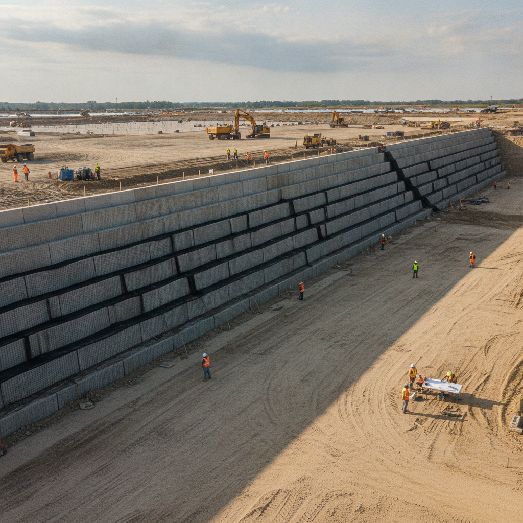
Retaining walls are engineered structures designed to hold back earth and maintain a difference in ground elevation. In data center construction, their role is strategic and multifaceted. The primary driver is the need to create a large, flat building pad on a site with natural slopes. A data center’s foundation requires uniform support, and any differential settlement can compromise sensitive equipment and structural integrity. The grading design must achieve this precise elevation, often requiring significant cuts and fills balanced across the property. Beyond creating the main pad, retaining walls maximize the usable area of a property. On a tight or irregularly shaped parcel, walls can be placed at property lines to eliminate sloped embankments that would otherwise consume valuable real estate. This allows for the full development of required access roads, security perimeters, utility yards for generators and cooling units, and stormwater management facilities. Effective footprint optimization is a key goal of the overall site plan design, and retaining walls are a powerful tool to achieve it.
Geotechnical Investigation: The Foundation of Wall Design
Comparison of Retaining Wall Systems for Data Centers
| Wall System | Typical Height Range | Surcharge Load Capacity | Construction Considerations |
|---|---|---|---|
| Cast-in-Place Concrete | 5 - 25 ft | High | Requires extensive formwork, rebar installation, and concrete curing time. Large footing can conflict with utilities. |
| Mechanically Stabilized Earth (MSE) | 10 - 80+ ft | Very High | Requires a large backfill zone for geogrid reinforcement. Rapid construction with specialized crews. Sensitive to proper backfill material and compaction. |
| Segmental Retaining Wall (SRW) | 3 - 30 ft (with geogrid) | Moderate to High | Flexible and aesthetically pleasing. Labor-intensive installation. Requires careful attention to base leveling and compaction. |
| Soldier Pile and Lagging | 10 - 50 ft | High | Ideal for excavation support in tight spaces. Can be noisy during pile driving. May require tiebacks for taller walls. |
| Soil Nail Wall | 10 - 60+ ft | High | Top-down construction method ideal for stabilizing existing slopes. Requires specialized drilling equipment. Not suitable for all soil types. |
The design of any significant retaining structure begins long before a single calculation is run. It starts deep in the ground with a comprehensive geotechnical investigation. This process, led by a qualified Geotechnical engineer, is non-negotiable for data center projects. It involves performing a series of soil boring test explorations across the site, particularly along the proposed wall alignment, to understand the subsurface conditions. Soil samples are collected at various depths and taken to a laboratory for testing. The resulting geotechnical soil report provides the design engineer with critical parameters, including soil classification, unit weight, shear strength, and the friction angle. This data is the foundation for all subsequent analysis, dictating the appropriate wall type, the magnitude of lateral earth pressures, and the structure’s required bearing capacity. The report will also assess groundwater levels and provide recommendations for managing subsurface water, which is a primary driver of wall failure. Without a thorough Soil Test, any design is based on assumptions, introducing unacceptable risk.
Analyzing Earth Pressures and Surcharge Loads
A retaining wall must be designed to resist immense lateral forces. The primary force is the lateral earth pressure exerted by the soil being retained. However, for a data center, the analysis is far more complex due to significant surcharge loads. These are additional vertical loads applied to the surface of the soil behind the wall, which translate into increased lateral pressure on the structure. Typical data center surcharges include the immense weight of backup power generators, large cooling towers, fuel tanks, and heavy electrical switchgear. Furthermore, access roads and fire lanes located near the top of a wall introduce live loads from heavy trucks and emergency vehicles. The civil engineering design must quantify these loads and incorporate them into the stability calculations. Failing to account for these surcharge loads can lead to overloading and catastrophic failure of the wall system, jeopardizing the entire facility.
Common Retaining Wall Systems for Data Center Applications
Several retaining wall systems are suitable for data center projects, with the final selection depending on wall height, soil conditions, site constraints, and project budget. Each has distinct advantages and engineering requirements that must be carefully evaluated during the site development planning phase. Key systems include: Cast-in-Place Concrete Cantilever Walls: These are rigid, monolithic structures made of reinforced concrete, shaped like an ‘L’ or inverted ‘T’. They are extremely durable and perform well for moderate heights (up to 20-25 feet). However, they require a large structural footing, which can create conflicts with underground utilities and require extensive excavation. Mechanically Stabilized Earth (MSE) Walls: MSE walls are composite systems consisting of precast concrete facing panels and layers of metallic or geosynthetic soil reinforcement (geogrid) extending into the backfill. They are highly flexible, can be built to great heights, and are often the most cost-effective solution for the large-scale grade changes common in data center development. Segmental Retaining Walls (SRWs): These are gravity-based systems built from high-strength, interlocking concrete blocks. They are typically used for shorter walls and are aesthetically versatile. For taller applications, they often incorporate geogrid reinforcement, functioning similarly to an MSE wall. Their structural design is governed by industry standards from the National Concrete Masonry Association (NCMA). Soldier Pile and Lagging Walls: This system involves driving or drilling vertical steel piles (H-piles) into the ground and placing lagging (typically timber or concrete panels) between them as excavation proceeds. They are excellent for projects with tight site constraints or where excavation support is needed adjacent to existing structures, but may not offer the finished aesthetic desired for a primary site feature.
Critical Design Factors: Stability and Drainage
Regardless of the wall system chosen, the design must satisfy fundamental stability requirements. The analysis, performed by a Professional Engineer, verifies the wall is safe against three primary failure modes: overturning, sliding, and bearing capacity failure. Additionally, a global stability analysis is performed to ensure that the wall and the entire soil mass behind it will not fail along a deep-seated slip surface. These calculations are complex and rely heavily on the data from the geotechnical investigation. Equally important is the drainage design. Water trapped in the soil behind a retaining wall exerts immense hydrostatic pressure, which is often the root cause of wall failures. A robust subsurface drainage system is not optional; it is a critical component. This typically includes a chimney drain of clean, crushed stone directly behind the wall, a perforated pipe at the base to collect water, and weep holes or a connection to the site’s main stormwater management system to carry the water away. Proper drainage relieves this pressure and is essential for the long-term performance and safety of the structure.
RSP Engineers’ Approach to Retaining Wall Design
At RSP Engineers, we treat retaining walls as the critical infrastructure they are. Our process is integrated and rigorous, ensuring every design is safe, compliant, and cost-effective. We begin with a thorough review of the client’s programmatic needs and the site’s constraints, followed by close coordination with the Geotechnical engineer to define the scope of the subsurface investigation. This ensures we get the precise data needed for an efficient design. Our team then performs a detailed alternatives analysis, comparing wall systems based on performance, cost, and constructability. Once a system is selected, we execute a comprehensive structural design, including all stability and global analyses. This design is seamlessly integrated with the overall site plan design, ensuring harmony with the site’s grading, utility coordination, and stormwater management strategy. We manage the entire permitting process, preparing detailed drawings and calculations for agency review and responding to comments to secure timely approvals. Finally, we provide Construction Management Services to ensure the wall is built in strict accordance with the design specifications.
Avoiding Common Pitfalls in Data Center Wall Construction
Even a perfect design can be compromised by poor construction practices. Several common issues can jeopardize the integrity of a retaining wall on a data center site. The most frequent is inadequate backfill and compaction. The soil placed behind the wall must be of the correct type and compacted in thin lifts to the specified density to achieve the designed strength. Another major pitfall is the failure to properly install the drainage system or allowing it to be clogged with sediment during construction. Other issues include deviating from the design without the engineer’s approval, such as changing the geogrid length in an MSE wall, or applying unplanned surcharge loads near the wall before it has developed its full strength. Close observation by the design engineer or a qualified inspector during construction is critical to prevent these errors. This is a key component of our construction administration services, providing quality assurance that protects the owner’s investment.
Partner with RSP Engineers for Your Mission-Critical Site Development
Designing and permitting retaining walls for data centers requires a deep understanding of soil mechanics, structural engineering, and the complex regulatory landscape of Florida. The stakes are too high for a one-size-fits-all approach. RSP Engineers provides the expert site engineering services needed to navigate these challenges, from initial feasibility and geotechnical coordination to final construction oversight. Our team of Florida Licensed Engineers has the experience to deliver a safe, compliant, and cost-effective design that protects your investment. If you are planning a mission-critical project, contact us today to discuss how our expertise in site development, stormwater management, and structural design can ensure your project is built on a solid foundation.
Building a Foundation for Digital Infrastructure
In conclusion, retaining walls are not an afterthought in data center design; they are enabling structures that make challenging sites viable. A successful project hinges on a design process that is rooted in a thorough geotechnical investigation, accurately accounts for all site-specific surcharge loads, and incorporates a robust drainage design. The selection of the appropriate wall system has significant impacts on the project’s budget, schedule, and long-term performance. Ultimately, the stability of a multi-million dollar data center can depend on the integrity of the earth retention system supporting it. Partnering with an experienced civil engineering firm near me that understands the nuances of mission-critical site development is the best way to manage risk and ensure a successful outcome.
FAQs
-
The maximum height depends on the wall type and subsurface soil conditions. Cast-in-place walls are typically limited to around 25 feet, while MSE walls can be engineered to heights exceeding 80 feet. Any tall wall requires an extensive geotechnical analysis and a highly specialized structural design to ensure global stability.
-
By far, the most common cause of failure is excessive hydrostatic pressure due to an inadequate or non-existent subsurface drainage design. Water saturation dramatically increases the load on the wall and can reduce the shear strength of the soil, leading to a stability failure.
-
Absolutely. The retaining wall is a fundamental part of the site’s topography and directly influences surface runoff patterns. The overall stormwater management plan must account for how water will be collected from the top of the wall and the area below it, integrating the wall’s subsurface drainage outlet into the larger conveyance system.