
Data Center Generator Fuel Systems: Civil Engineering Design Guide
A guide to the civil engineering design of data center generator fuel systems. Learn about bulk storage, containment, permitting, and site layout from Florida’s mission-critical experts.
Site Layout and Generator Yard Integration
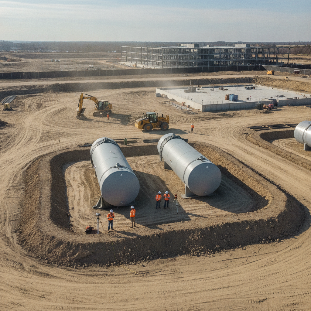
The generator fuel system is not an isolated component; it must be seamlessly integrated into the overall data center site development plan. The location of the generator yard and its associated fuel tanks is one of the first major decisions. This placement is driven by several factors, including required separation distances from the main building for fire safety, acoustic considerations, and security protocols. A key civil engineering task is ensuring efficient and safe access for large fuel tanker trucks, which requires careful planning of on-site roadways, turning radii, and dedicated offloading pads. Effective utility coordination is paramount. The fuel system, with its underground piping and electrical conduits for monitoring systems, must coexist with a dense network of other site utilities, including primary power, communications, water, and sewer. Our role as a Civil Engineer near me involves creating a comprehensive utility plan that prevents clashes and ensures proper clearances are maintained. This early-stage planning minimizes costly construction-phase conflicts and ensures the long-term serviceability of all site infrastructure, forming the foundation of a successful site plan design.
Bulk Fuel Storage: Aboveground vs. Underground Tanks
AST vs. UST: Key Civil Engineering Considerations
| Consideration | Aboveground Storage Tanks (ASTs) | Underground Storage Tanks (USTs) |
|---|---|---|
| Installation & Site Impact | Requires significant surface footprint; simpler foundation design; less excavation. | Minimal surface footprint; requires extensive excavation, dewatering, and specialized backfill. |
| Secondary Containment | Requires large, poured concrete or steel dike containment area (110% capacity + freeboard). | Achieved via double-walled tank and piping with interstitial monitoring sensors. |
| Maintenance & Inspection | Easier visual inspection of tank shell and connections; containment area requires regular water removal. | Requires specialized equipment for internal inspection; relies heavily on electronic monitoring for leak detection. |
| Permitting Complexity | Focus on SPCC plan, fire marshal review for separation distances, and stormwater integration. | Focus on FDEP registration, leak detection plans, and long-term monitoring compliance. |
| Environmental Risk Profile | Spills are immediately visible but can spread over a large surface area if containment fails. | Leaks are contained but can go undetected longer, potentially leading to significant soil/groundwater contamination. |
| Utility Coordination | Fewer underground conflicts, but surface layout must accommodate large containment area. | High potential for conflict with other underground utilities; requires precise 3D modeling and coordination. |
A fundamental design choice is whether to use Aboveground Storage Tanks (ASTs) or Underground Storage Tanks (USTs) for bulk diesel storage. Each option presents distinct advantages and challenges that directly impact the site development process, budget, and long-term operational plan. ASTs are generally less expensive to install and allow for easier visual inspection and maintenance. However, they occupy a significant physical footprint and are subject to stringent fire code separation requirements and visual screening from public view. Conversely, USTs conserve valuable surface space, which can be critical on compact data center campuses. They offer enhanced security and protection from physical damage. The trade-offs include higher installation costs due to excavation and specialized backfill, more complex leak detection monitoring systems, and more challenging maintenance access. The decision is also heavily influenced by local regulations and the project’s specific risk tolerance, requiring a thorough analysis of the Florida Building Code and environmental regulations during the initial design phase.
Secondary Containment and Spill Prevention (SPCC)
Regardless of tank type, robust secondary containment is non-negotiable and a core focus of civil engineering design. For ASTs, this typically involves a poured-in-place concrete containment basin or a pre-engineered steel dike system. The containment volume must, at a minimum, hold 110% of the volume of the largest single tank within the containment area, plus displacement for other tanks and sufficient freeboard to account for rainfall. This requirement is central to the facility’s Spill Prevention, Control, and Countermeasure (SPCC) plan, a federal requirement regulated by the EPA. The design of the containment area also incorporates critical drainage design elements. A dedicated sump and pump system is required to manage accumulated stormwater, often with sensors to detect the presence of fuel before discharging water. The concrete and any joint sealants must be specified to be impervious to diesel fuel. For USTs, secondary containment is typically achieved through double-walled tank and piping construction, coupled with interstitial monitoring sensors that provide early warnings of a potential leak, a critical component of the environmental permitting strategy.
Fuel Piping and Distribution Design
The network of pipes that transports fuel from the bulk storage tanks to the individual generator day tanks is a critical piece of infrastructure. The civil engineering scope includes determining the optimal routing for these pipelines to minimize length, avoid conflicts with other utilities, and protect them from damage. In most mission-critical applications, double-walled piping is the standard, providing an integral layer of secondary containment for the distribution network. Proper utility coordination is essential during this phase. Fuel lines must be installed with specified separation from high-voltage electrical conduits and communication lines. The design includes detailed trenching plans, specifying the pipe bedding, backfill material, and compaction requirements to ensure long-term structural integrity. Leak detection systems, with sensors placed at low points and within containment sumps, are integrated into the design and tied into the facility’s building management system (BMS) for constant monitoring, a key part of the overall site engineering services package.
Refueling Access and Traffic Flow Management
A data center’s fuel system must be easily and safely refuelable, often under adverse conditions. The civil design must accommodate the dimensions and turning capabilities of large tanker trucks. This involves designing access roads with adequate width, pavement structure, and, most importantly, sufficient turning radii to prevent trucks from driving over curbs or softscapes. A dedicated, clearly marked concrete offloading pad is designed at the fill connection point to provide a stable, level surface. This aspect of site plan design also incorporates safety features like protective bollards to prevent accidental vehicle impact with tanks or critical piping. The drainage from the offloading pad is carefully managed, often directing any potential small spills to an oil-water separator before entering the main stormwater management system. This proactive approach to traffic and safety is a hallmark of quality mission-critical design and is reviewed closely during the permitting process.
Fire Separation and Code Compliance
Ensuring compliance with fire codes is a primary responsibility of the design team. The National Fire Protection Association (NFPA) codes, particularly NFPA 30 (Flammable and Combustible Liquids Code) and NFPA 37 (Standard for the Installation and Use of Stationary Combustion Engines and Gas Turbines), dictate the minimum required separation distances. These distances apply between fuel tanks, property lines, public ways, and important buildings, including the data center itself. These fire separation requirements directly influence the generator yard’s location and layout, making it a critical early consideration in the site development process. Achieving zoning compliance and securing approval from the local fire marshal depends on demonstrating that these setbacks are met. The civil engineering plans must clearly delineate these separation zones and incorporate any required fire-rated barriers or walls if distances cannot be fully met due to site constraints, a common issue requiring close agency review and collaboration.
RSP Engineers’ Approach to Fuel System Design
At RSP Engineers, our process begins with a comprehensive site assessment and a deep dive into the client’s operational requirements and risk tolerance. We model the site constraints, including setbacks, easements, and existing utilities, to determine the optimal location and configuration for the generator yard. Our team of Florida Licensed Engineers works collaboratively with mechanical and electrical engineers to ensure the fuel system design is fully integrated with the generator specifications and facility-wide monitoring systems. We manage the entire lifecycle, from initial concept and site plan design to the preparation of detailed construction documents. A significant part of our value lies in navigating the complex web of regulations. We lead the environmental permitting process with agencies like the FDEP and local water management districts, and we coordinate directly with fire marshals and building departments to secure all necessary approvals. Our goal is to deliver a design that is not only compliant and resilient but also cost-effective and constructible.
Common Challenges in Fuel System Site Design
Even with careful planning, data center fuel system projects can encounter challenges. Unforeseen subsurface conditions, such as a high water table or poor soil bearing capacity, can complicate tank foundation design and require costly soil improvements or specialized dewatering during construction. Another common issue is discovering undocumented utilities during excavation, which can cause significant delays and require immediate redesign. This highlights the importance of thorough due diligence, including subsurface utility engineering (SUE) investigations. During the agency review process, regulators may have specific comments on stormwater discharge from containment areas or require additional fire protection measures. Underestimating the space required for tanker truck maneuvering is another frequent pitfall that can lead to operational headaches post-construction. Proactive engagement with all stakeholders and a design process that anticipates these potential issues are key to mitigating risks and keeping the project on schedule.
Partner with RSP Engineers for Your Mission-Critical Project
Designing and permitting a data center fuel system requires specialized expertise that goes beyond standard commercial site design. The stakes are higher, the regulations are stricter, and the need for precision is absolute. RSP Engineers provides the expert site engineering services needed to navigate these complexities. Our team has extensive experience in mission-critical site development, from initial due diligence and master planning to detailed utility coordination and securing complex environmental and building permitting approvals across Florida. We ensure your facility’s power backbone is built on a foundation of resilient and compliant civil engineering.
Conclusion: Engineering Resilient Fuel Infrastructure
The reliability of a data center is directly tied to the quality of its underlying infrastructure. A well-designed generator fuel system is a critical component of this infrastructure, ensuring continuous operation when it matters most. Achieving this requires a holistic approach to civil engineering that balances site logistics, regulatory compliance, and operational resilience. From the strategic decisions in site development to the technical details of stormwater management and containment design, every element must be meticulously planned and executed. Proactive engagement with experienced engineers is the best way to navigate the permitting process and deliver a fuel system that truly supports mission-critical uptime.
FAQs
-
In Florida, as in most jurisdictions following EPA guidelines, secondary containment for an AST system must be sized to hold a minimum of 110% of the volume of the largest tank within the containment area. The calculation must also account for the volume displaced by any other tanks or equipment inside the berm and include additional volume, or ‘freeboard,’ for precipitation from a significant storm event, which is a key part of the stormwater management plan.
-
The primary challenge is managing the density of underground infrastructure in a modern data center site. The fuel piping must be routed to avoid clashes with high-voltage electrical duct banks, communication conduits, water mains, and gravity-fed sewer and storm drains. Maintaining required vertical and horizontal separation distances is critical for safety and future maintenance. This makes detailed 3D utility coordination and clash detection modeling an essential part of the design process.
-
Typically, the generator yard is not permitted separately but is included as part of the overall site’s Environmental Resource Permit (ERP) or other relevant stormwater management permit. The design must show how stormwater that falls within the secondary containment area is managed (tested and pumped out) and how runoff from the surrounding yard areas is collected and treated within the site’s master drainage system before discharge.