
Data Center Flood Routing Analysis
A technical guide for data center developers on flood routing analysis, hydrograph attenuation, and stormwater management for mission-critical sites in Florida. Learn how RSP Engineers protects your i
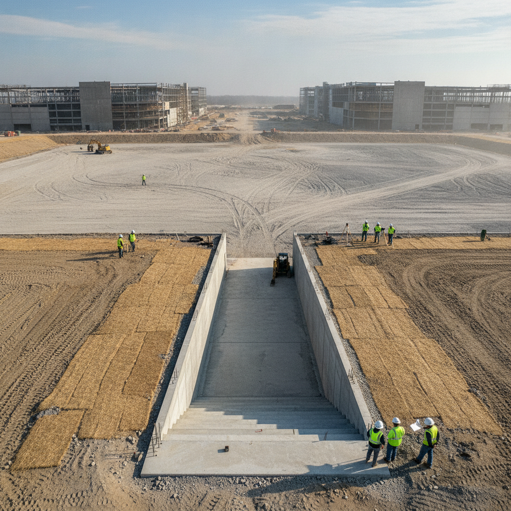
Understanding Flood Hydrographs and Peak Flow Attenuation
The foundation of any flood routing analysis is the flood hydrograph. A hydrograph is a graph that plots the rate of stormwater runoff (flow) over time for a specific location. When rain falls on an undeveloped site, much of it infiltrates the ground, resulting in a slow, spread-out hydrograph with a low peak flow. In contrast, a data center campus—with its vast rooftops, parking lots, and roadways—creates massive impervious surfaces. This causes a much larger volume of water to run off much faster, creating an inflow hydrograph with a high, sharp peak. The primary goal of a stormwater management system is to capture this runoff and release it slowly, a process known as peak flow attenuation. To achieve this, civil engineers must design a system that reduces the post-development peak discharge rate to match pre-development levels, a common requirement for securing a permit submittal from Florida’s Water Management Districts. This involves calculating the site’s time of concentration—the time it takes for water to travel from the most hydraulically distant point of the drainage area to the outlet. By strategically designing detention ponds and conveyance systems, we can lengthen this time, effectively flattening the outflow hydrograph and protecting both the site and downstream properties from erosive and damaging floodwaters.
Reservoir Routing: The Core of On-Site Stormwater Detention
Key Parameters in Level-Pool Routing Analysis
| Parameter | Description | Impact on Data Center Site Design |
|---|---|---|
| Inflow Hydrograph | The time-distributed runoff entering the pond from the site's drainage area. | Determines the total volume of water the pond must manage. Larger impervious areas (roofs, parking) create higher, faster peak inflows. |
| Stage-Storage Relationship | A curve defining the volume of water the pond can hold at any given water elevation (stage). | Directly tied to the pond's physical footprint and depth. A larger required storage volume may reduce the usable area for development. |
| Stage-Discharge Relationship | A curve defining the rate of outflow from the pond's outlet structure at any given water elevation. | Dictated by the size and type of orifices and weirs. This is the primary mechanism for controlling and attenuating the peak outflow. |
| Initial Water Surface Elevation | The water level in the pond at the beginning of the storm simulation. | Critical for wet detention systems or when analyzing back-to-back storm events. A higher starting elevation reduces available storage capacity. |
| Routing Time Step (Δt) | The computational time increment used in the routing calculation. | A technical modeling parameter. A smaller time step provides greater accuracy but requires more computational power. It must be small enough to accurately define the hydrograph shape. |
The workhorse of peak flow attenuation on a data center site is the detention pond, which functions as a temporary reservoir. The process of modeling how a flood wave is stored and released from this pond is called reservoir routing. The most common method used in Florida civil engineering is level-pool routing, which assumes the water surface within the pond is perfectly horizontal at all times. This method relies on the continuity equation: Inflow - Outflow = Change in Storage. Essentially, we model the relationship between the water depth (stage), the volume of water the pond can hold (storage), and the rate at which water can exit through the outlet structure. The design of the outlet control structure is critical. It typically consists of a combination of weirs and orifices engineered to specific elevations and sizes. During a storm, as the water level in the pond rises, the outflow rate increases according to the hydraulic properties of these outlets. By carefully calibrating the pond’s volume and the outlet’s configuration, we can ensure the peak outflow rate is significantly lower than the peak inflow rate. This detailed drainage design is fundamental to demonstrating compliance and ensuring the system performs predictably during major storm events.
Channel Routing: Analyzing Conveyance Systems and Downstream Impacts
While ponds manage storage, the network of pipes, culverts, and swales that move water across the site must also be analyzed. This is known as channel routing. Unlike a reservoir where water pools, water in a channel is constantly moving, and its hydrograph changes shape as it travels. The channel’s physical characteristics—its slope, cross-sectional shape, and roughness (e.g., concrete pipe vs. vegetated swale)—influence the timing and magnitude of the flood wave. A key consideration in channel routing is ensuring the conveyance system has adequate capacity to handle the routed flows without overtopping and causing localized flooding on-site. Furthermore, this analysis is vital for evaluating downstream impacts. A successful site development project must not create adverse flooding conditions for neighboring properties. Regulatory agencies in Florida pay close attention to the timing and peak flow of the discharge leaving the project boundary. Sophisticated H&H models are used to simulate how the attenuated hydrograph from the site will combine with flows in the downstream receiving system, ensuring that the project does not worsen existing conditions. This proof of no adverse impact is a cornerstone of the agency review process.
Multi-Basin Routing for Large Data Center Campuses
Data center campuses are rarely a single, simple drainage area. They are often sprawling sites composed of multiple drainage basins, each with its own collection system and potentially its own stormwater pond. In these scenarios, a multi-basin routing analysis is required. This is a far more complex undertaking, as the outflow from an upstream pond becomes the inflow for a downstream conveyance channel or another pond. The analysis must account for the travel time and attenuation that occurs between each element in the series. A critical aspect of multi-basin routing is analyzing the potential for peak flow coincidence. If the peak discharges from two separate basins arrive at a single confluence point simultaneously, the combined flow can overwhelm the downstream system. A skilled civil engineering team will model these interactions carefully, sometimes adjusting pond outlet structures or channel designs to stagger the timing of peak flows. This level of detailed utility coordination and drainage planning prevents compounded flooding and is essential for the resilience of a large-scale campus.
Modeling Extreme Events: Emergency Spillway and Dam Breach Analysis
A data center’s stormwater system must be designed for resilience, which means planning for events that exceed the design storm (e.g., a 25-year or 100-year storm event). An emergency spillway is a critical safety feature of a detention pond. It is a broad, armored channel positioned at an elevation above the normal maximum water level but below the top of the pond embankment. Its purpose is to provide a controlled, non-erosive path for water to exit the pond during an extreme storm that overwhelms the primary outlet structure, preventing a catastrophic failure of the embankment. For very large ponds or those classified as having a high downstream hazard potential, regulatory agencies may require a formal dam breach analysis. This intensive modeling exercise simulates a sudden failure of the pond embankment, creating an inundation map that shows the extent and depth of flooding downstream. This analysis helps verify that the design complies with safety regulations and that an emergency action plan can be developed if necessary. This level of scrutiny is increasingly common for mission-critical site development projects where failure is not an option.
The Role of Hydrologic and Hydraulic (H&H) Modeling Software
Modern flood routing analysis is impossible without advanced software tools. Engineers use sophisticated Hydrologic and Hydraulic (H&H) modeling programs like the Interconnected Channel and Pond Routing (ICPR), HEC-RAS, and the EPA Storm Water Management Model (SWMM) to build detailed digital representations of the site. These models incorporate rainfall data, soil types, land cover, and the precise geometry of every pipe, channel, and pond. This allows for the simulation of complex stormwater management systems under various storm scenarios. These models are not just design tools; they are essential for communication and permitting. The outputs—hydrographs, water surface profiles, and inundation maps—provide the verifiable proof needed to demonstrate to regulatory agencies that the proposed drainage design meets all applicable codes and performance standards. For a data center developer, a well-documented H&H model is a key asset that validates the site’s resilience and streamlines the path to securing construction approvals.
RSP Engineers’ Approach to Flood Routing and Site Resilience
At RSP Engineers, our approach to flood routing for data centers is rooted in a philosophy of proactive risk mitigation. We begin with a thorough site assessment, identifying topographical constraints, soil characteristics, and downstream conveyance limitations. Our process involves creating detailed H&H models early in the design phase, allowing us to test various stormwater management strategies and optimize the site layout. We believe in an iterative design process, refining the drainage design and pond configurations to achieve regulatory compliance while maximizing the client’s usable land. This detailed modeling becomes the backbone of our permit submittals to agencies like the Florida Department of Environmental Protection (FDEP) and local Water Management Districts. By providing clear, defensible analysis, we streamline the agency review process and reduce the likelihood of costly requests for additional information. Our goal is to deliver a resilient site engineered not just to pass a storm, but to ensure the operational continuity of the mission-critical facility it supports.
Common Challenges in Data Center Flood Protection Design
Even with sophisticated tools, designing these systems presents challenges. A common issue is underestimating the runoff from the massive, flat roofs typical of data centers, which can have a near-100% runoff coefficient. Another challenge is accurately modeling tailwater conditions—the water level in the downstream channel or system that receives the site’s discharge. High tailwater can submerge the outlet structure, severely reducing its discharge capacity and causing water to back up onto the site. Finally, value engineering efforts that reduce pond size or simplify outlet structures without rigorous re-analysis can introduce significant risk, compromising the integrity of the entire stormwater management system.
Secure Your Mission-Critical Infrastructure with Expert Civil Engineering
Protecting a multi-million dollar data center from flooding requires more than just a generic site plan. It demands specialized expertise in hydrologic modeling, hydraulic design, and Florida’s complex regulatory landscape. The team at RSP Engineers provides the rigorous flood routing analysis and comprehensive stormwater management design necessary to secure your investment. We partner with developers to navigate the complexities of permitting, optimize site layouts, and deliver resilient infrastructure built for long-term operational certainty. Don’t leave your critical facility’s resilience to chance. Contact us today to discuss your project’s unique challenges.
Conclusion: Proactive Flood Routing as an Investment in Uptime
Ultimately, a thorough flood routing analysis is not merely a line item in a construction budget or a hurdle in the permitting process. It is a fundamental investment in the long-term viability and uptime of a mission-critical facility. By accurately modeling how a site will behave in extreme weather, we can engineer robust drainage design solutions that provide predictable, reliable protection. For data center operators in Florida, where intense rainfall is a certainty, this proactive approach to civil engineering is the bedrock upon which digital fortresses are built, ensuring they remain secure, operational, and resilient for decades to come.
FAQs
-
A detention pond is designed to hold stormwater temporarily and release it slowly over time through a control structure; it is typically dry between storms. A retention pond is designed to hold a permanent pool of water and captures a specific volume of runoff, allowing it to percolate into the ground and evaporate, which provides significant water quality benefits. Many Florida systems are a hybrid, using a wet detention design.
-
Florida’s terrain is predominantly flat, and many natural drainage systems are already at capacity. State and local regulations mandate that new developments, especially large ones like data centers, do not increase the peak rate of stormwater runoff leaving the site. This prevents the project from causing or worsening downstream flooding and erosion. Proving this through accurate flood routing analysis is a critical requirement for obtaining an Environmental Resource Permit (ERP).
-
The analysis directly determines the required storage volume for the stormwater ponds. A larger required volume means a larger pond footprint, which in turn reduces the land available for buildings, equipment yards, and parking. Expert civil engineering aims to optimize the pond design (e. g. , making it deeper vs. wider) and integrate it efficiently into the overall site development plan to maximize usable space without compromising safety or compliance.