
Coordinating Civil and Plumbing Water Systems for Data Centers
A deep dive into the critical handoff between civil site utilities and building plumbing for data centers. Learn how to coordinate fire service, potable water, and sewer systems to avoid costly rework
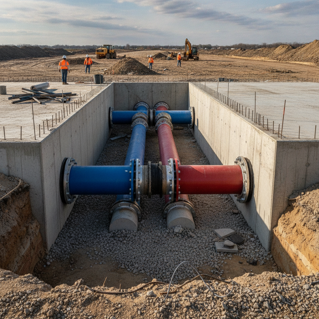
The Critical Handoff: Civil Site Utilities to Building Plumbing
The fundamental challenge lies in the division of scope between two distinct engineering disciplines. The civil engineering team designs all exterior utilities, including the routing of water mains, fire lines, and sewer systems from the public right-of-way to the building’s perimeter. Their work involves extensive utility coordination with public providers, securing easements, and navigating complex permitting processes. The plumbing engineer, conversely, designs all systems within the building envelope, from the point of entry to the final fixture or equipment connection. This handoff point is where ambiguity can lead to significant problems. A lack of early and continuous communication can result in mismatched pipe sizes, incompatible materials, or incorrect elevations, leading to field conflicts during construction. The design of these systems is governed by a complex web of codes and utility standards. Importantly, permitting requirements vary by jurisdiction, and every project team should confirm the applicable standards with the local, state, regional, and federal authorities that hold review authority over the site. This includes confirming specific requirements from the local water and sewer utility, the building department, and the fire marshal, as their standards dictate everything from backflow prevention to fire hydrant placement.
Defining the Five-Foot Line: Convention vs. Reality
Key Coordination Points for Data Center Water Systems
| System Component | Typical Civil Engineer Scope | Typical Plumbing Engineer Scope | Key Coordination Point |
|---|---|---|---|
| Potable Water Service | Tap at public main, service line to building, exterior meter vaults, site-level backflow preventers. | Interior piping from the 5' line, interior meters and backflow preventers, pressure reducing valves, distribution to fixtures and equipment. | Meter size and location; backflow preventer type and location; required service pressure. |
| Fire Protection Main | Tap at public main, private fire loop, fire hydrants, post-indicator valves (PIVs), line to building penetration. | Fire service entry piping, fire sprinkler riser, fire pump, interior sprinkler system, fire department connection (FDC). | Invert elevation and material at wall penetration; thrust block location vs. foundation; FDC location. |
| Sanitary Sewer Lateral | Sewer lateral from building exit to public main, manholes, cleanouts outside the building. | All interior sanitary drainage piping, floor drains, connection to grease traps (if any), pipe exiting the building foundation. | Invert elevation, size, and material of the pipe at the building exit point. |
| Storm Drainage | Roof drain leader connection points, site grading, catch basins, underground storm pipes, stormwater management facilities (ponds, vaults). | Roof drains, interior storm leaders, and connection to the storm sewer system at the base of the building. | Location and invert elevation of each roof drain leader connection point. |
| Industrial Wastewater | Discharge line from building to public sewer, exterior sampling manholes, oil-water separators (if exterior). | Collection of cooling tower blowdown or other process water, interior pre-treatment systems, discharge pump systems. | Discharge flow rates, water quality parameters, and compliance with utility provider's pre-treatment requirements. |
By convention, the dividing line between civil and plumbing scope is often defined as five feet outside the building foundation wall. The civil engineer’s design typically terminates at this point, while the plumbing engineer’s design begins. However, this is a guideline, not a universal rule. The actual point of connection (POC) can be influenced by project-specific factors, such as the location of meter vaults, backflow prevention assemblies, or fire department connections (FDCs). Successful projects define this boundary explicitly in the contract documents and on the design drawings. The site development plans should clearly show the termination point of the civil utilities, including the precise horizontal location, invert elevation, pipe material, and size. The plumbing plans must show the corresponding connection point with matching specifications. This level of detail prevents assumptions and ensures the contractor has a clear, coordinated set of plans to build from, minimizing requests for information (RFIs) and potential change orders related to utility stubs.
Coordinating Potable Water Service and Metering
Potable water service for a data center serves both domestic needs (restrooms, break rooms) and critical mechanical systems, such as cooling tower makeup water. The coordination begins with the civil engineer establishing the connection to the public water main and designing the service line to the building. A key coordination point is the water meter and the required backflow preventer. The location of these devices—whether in an exterior vault or inside the building—is a critical decision with cost, maintenance, and regulatory implications. The civil and plumbing teams must collaborate on the meter sizing, which is based on the building’s total water demand calculated by the plumbing engineer. They must also agree on the location and type of backflow prevention assembly required by the local utility provider. The civil engineering plans will show the device if it’s located on-site but outside the building, while the plumbing plans will detail it if it’s inside. This coordination ensures that pressure loss through the meter and backflow device is accounted for in the building’s hydraulic calculations, guaranteeing adequate pressure at the point of use.
Fire Protection Service: From Public Main to Riser Room
Perhaps the most critical utility handoff is the fire protection service. The civil engineer is responsible for designing the private fire main from the public connection to the building entry point, including on-site fire hydrants and post-indicator valves (PIVs). The design must meet the fire flow requirements determined by the building’s size, construction type, and hazard classification, often dictated by NFPA standards and the local fire marshal. The handoff to the plumbing or fire protection engineer occurs where the fire line penetrates the building foundation and connects to the fire sprinkler riser. Key coordination items include: Pipe Material: Ensuring the exterior ductile iron or C900 PVC pipe is properly transitioned to the interior steel pipe using approved fittings. Thrust Blocks: The civil engineer designs concrete thrust blocks on the exterior to resist water pressure at bends and fittings, but coordination is needed to ensure they don’t conflict with the building foundation. Wall Penetration: The sleeve for the pipe penetration through the foundation must be correctly sized and waterproofed, a detail that requires input from the structural engineer, civil engineer, and plumbing engineer. Riser Room Location: The fire line’s entry point must align precisely with the location of the fire riser room inside the building.
Sanitary Sewer and Industrial Wastewater Coordination
Coordinating the sanitary sewer connection involves ensuring a continuous gravity-powered flow from the building to the public main. The plumbing engineer designs the building’s drainage system, terminating with a single connection point exiting the foundation. The civil engineer then designs the sewer lateral from that point to the public sewer. The most critical piece of information is the invert elevation (the elevation of the bottom-inside of the pipe) at the building exit. The civil engineer uses this starting elevation to design the sewer lateral with the proper slope to ensure positive flow, avoiding conflicts with other underground utilities. For data centers with extensive water-based cooling, a separate industrial wastewater or pre-treatment system may be required for cooling tower blowdown. This involves close coordination on discharge permits, sampling manholes, and compliance with NPDES (National Pollutant Discharge Elimination System) regulations, which often requires a coordinated effort between the civil, plumbing, and process mechanical engineers to meet the sewer authority’s requirements.
Our Process: An Integrated Approach to Utility Design
At RSP Engineers, we mitigate the risks associated with the civil-to-plumbing handoff through a proactive and integrated approach. Our process begins during the initial site development and due diligence phase, where we identify all utility providers and their specific technical standards. We initiate joint design meetings with the project’s plumbing and mechanical engineers early in the schematic design phase, long before construction documents are started. During these meetings, we establish a ‘responsibility matrix,’ clearly documenting the scope for each discipline and identifying all critical handoff points. We use shared digital models to overlay site utility plans with building foundation and plumbing plans, allowing us to detect clashes and misalignments virtually. This collaborative process, combined with rigorous quality control reviews, ensures that our civil engineering plans are fully coordinated with the building systems, providing the contractor with a clear and buildable design that minimizes field changes and supports the project’s aggressive schedule.
Common Coordination Gaps and How to Avoid Them
Despite best intentions, coordination gaps can still occur. One of the most common issues is a discrepancy in the fire service line’s invert elevation. The civil engineer may design the line to clear other site utilities, while the plumbing engineer assumes a different elevation based on the interior riser room layout. This can only be resolved with a costly field modification. This is avoided by establishing the final riser room floor elevation early and sharing it between disciplines. Another frequent problem is a mismatch in pipe materials or joint types at the connection point. For example, the civil plans may specify a push-on joint for a ductile iron pipe, while the plumbing plans require a flanged connection for the transition inside the building. Resolving this in the field can delay pressure testing and subsequent construction activities. The solution is to explicitly detail the connection on both sets of plans, including the required transition coupling or adapter fitting. Early and detailed utility coordination is the key to preventing these and other avoidable conflicts.
Your Partner in Mission-Critical Site Development
The success of a data center project hinges on flawless execution, and that begins with a perfectly coordinated design. At RSP Engineers, we specialize in the complex site development and utility coordination required for mission-critical facilities. Our team of experienced engineers understands the critical handoff between site and building systems. We provide comprehensive civil engineering, permitting, and construction administration services to ensure your project’s water, sewer, and fire protection systems are designed and built right the first time. Don’t let a preventable utility conflict derail your project schedule. Contact RSP Engineers today to discuss how our expertise can ensure a seamless integration of your site and building infrastructure.
Conclusion
The interface between civil and plumbing engineering is a critical control point in the development of any data center. While often treated as a simple handoff, it is a complex intersection of different codes, materials, and design responsibilities. By prioritizing early collaboration, establishing clear lines of responsibility, and focusing on the technical details of each connection, development teams can avoid costly field conflicts and ensure the reliability of essential water and wastewater systems. Effective utility coordination is not just a best practice; it is a fundamental requirement for successful site development and the long-term operational integrity of any mission-critical facility.
FAQs
-
This is a shared responsibility. The type of backflow preventer required is determined by the local water authority’s cross-connection control regulations. The location (inside the building vs. in an outside vault) is a design decision based on project constraints, cost, and maintenance access, and must be agreed upon by the civil engineer, plumbing engineer, and owner.
-
If not caught during design review, this will cause a field conflict. The contractor will issue an RFI, and the engineers will need to specify an approved transition fitting or coupling that is compatible with both pipe materials and rated for the required pressure. This can cause delays while the correct part is procured. Proper utility coordination during the design phase prevents this.
-
The civil engineer obtains available water pressure data from the public utility. The plumbing engineer uses this information, accounting for pressure losses through the meter, backflow preventer, and site piping, to determine if a booster pump is needed inside the building to meet the pressure requirements of fixtures and equipment, especially in multi-story facilities.